Ergonomic Recommendations
Product Reference Guide
35
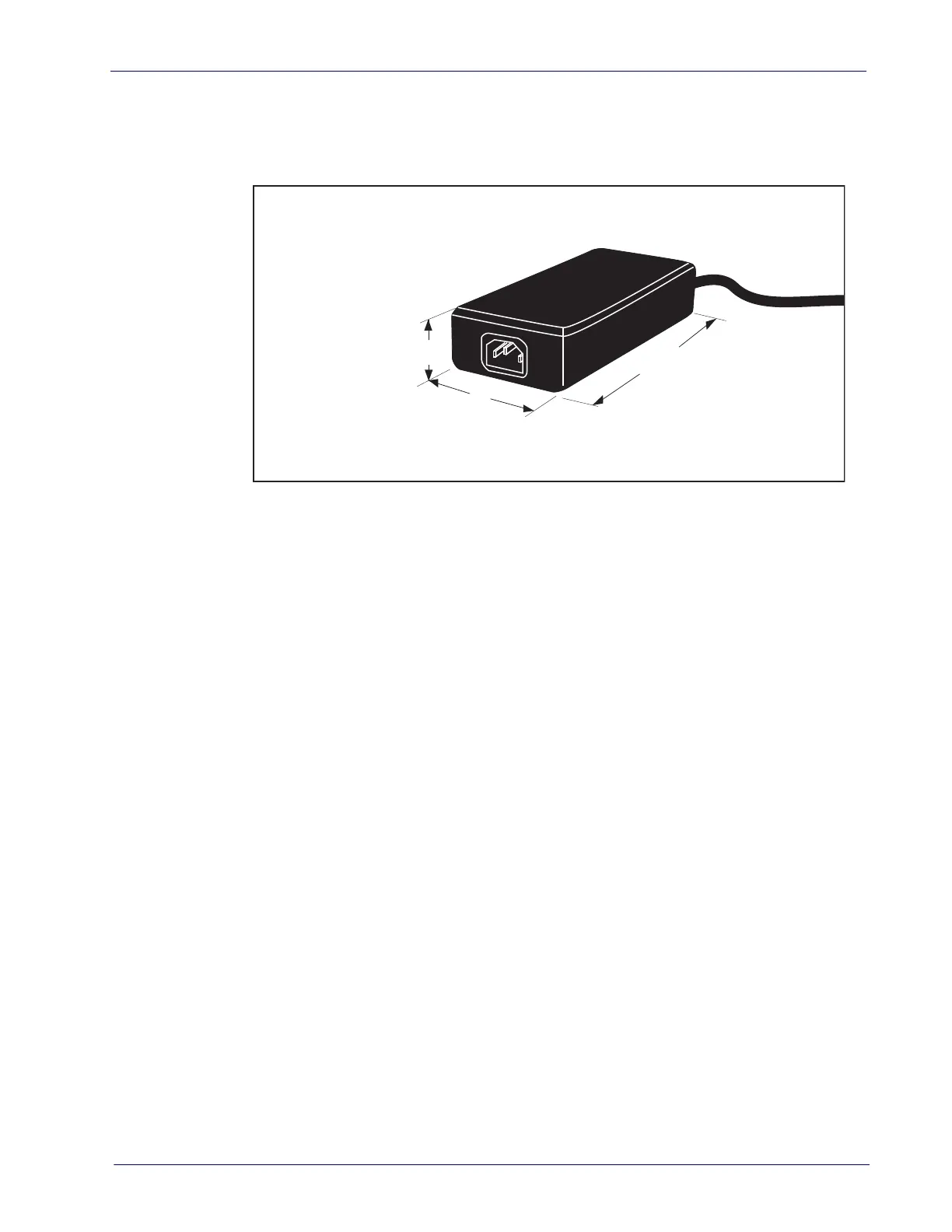
AC/DC Adapter
Figure 18 provides physical dimensions for the AC/DC Adapter (part number
90ACC0078).
Figure 18. Physical Measurements: AC/DC Adapter
Grounding
The AC/DC Power Supply should have an AC outlet with a clean earth ground. If
you are not sure how to verify the amount of electrical noise (interference) on
the power line, ask a qualified electrician to measure the input line voltage.
2.2 Connect cables
Follow these steps to ensure that your unit has arrived undamaged and is fully
functional before installing it in the counter and connecting it to your POS sys
-
tem.
1. Place the unit on the checkstand next to the counter cutout.
2. Route the cables up through the cutout and connect the scanner and scale
interface cable(s), and Remote Scale Display cable (optional) to the scan
-
ner. Some POS terminals require two interface cables; one for the scanner
interface and one for the scale interface. Refer to
Figure 19 for cable con-
nection locations.
If you have a scanner with no scale, there will be only one interface cable to the
POS terminal.
3. Connect the power cord to the scanner and route the other end down
through the checkstand to the AC power outlet. DO NOT plug the power
cord in at this time.
4. OPTIONAL — Route your EAS antenna cable down through the checkstand
cutout. (Reference your EAS controller’s setup instructions for proper EAS
antenna installation.)
3.35"
(8.5 cm )
1.97"
(5 cm )
1.23"
(3.1 cm)

 Loading...