Part III: Background and Concepts
Applications of VITS Signals
A brief waveform distortion
CLDI
10T pulse is made up of a sine
pulse and a chrominance packet with a sine-squared
envelope (CCIR 17)
level chrominance bar (CCIR 331)
Luminance nonlinear distortion
step luminance staircase signal
In Channel Frequency Response
Differential Gain and Differential Phase
luminance steps superimposed with modulated
chrominance (CCIR 330)
Intermodulation Distortion
level chrominance bar (CCIR 331)
VITS test signals combine several types of test signals into one composite signal. This composite test signal is
inserted in an empty or unused line of the vertical blanking interval behind the field sync pulse. The line
position of these VITS signals are typically off the viewable portion of your television screen. These signals are
inserted at the top of every field signal. They are specifically designed to meet non-intrusive measurement
practices.
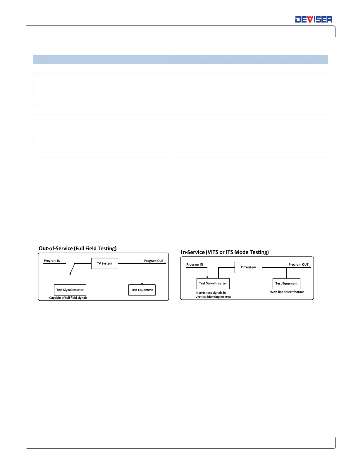
Gated video signal measurements need VITS signal generators and/or test signal inserters. VITS signal
generators are used to generate basic test signals. The video test signal inserter is typically used to insert a
VITS signal on the blanking line of a video signal. The following two figures illustrate the signal connection
methods of out-of-service testing and/or in-service testing.