Part III: Background and Concepts
Then, the common troubleshooting method prevails, hunting down the impairment going down a specific
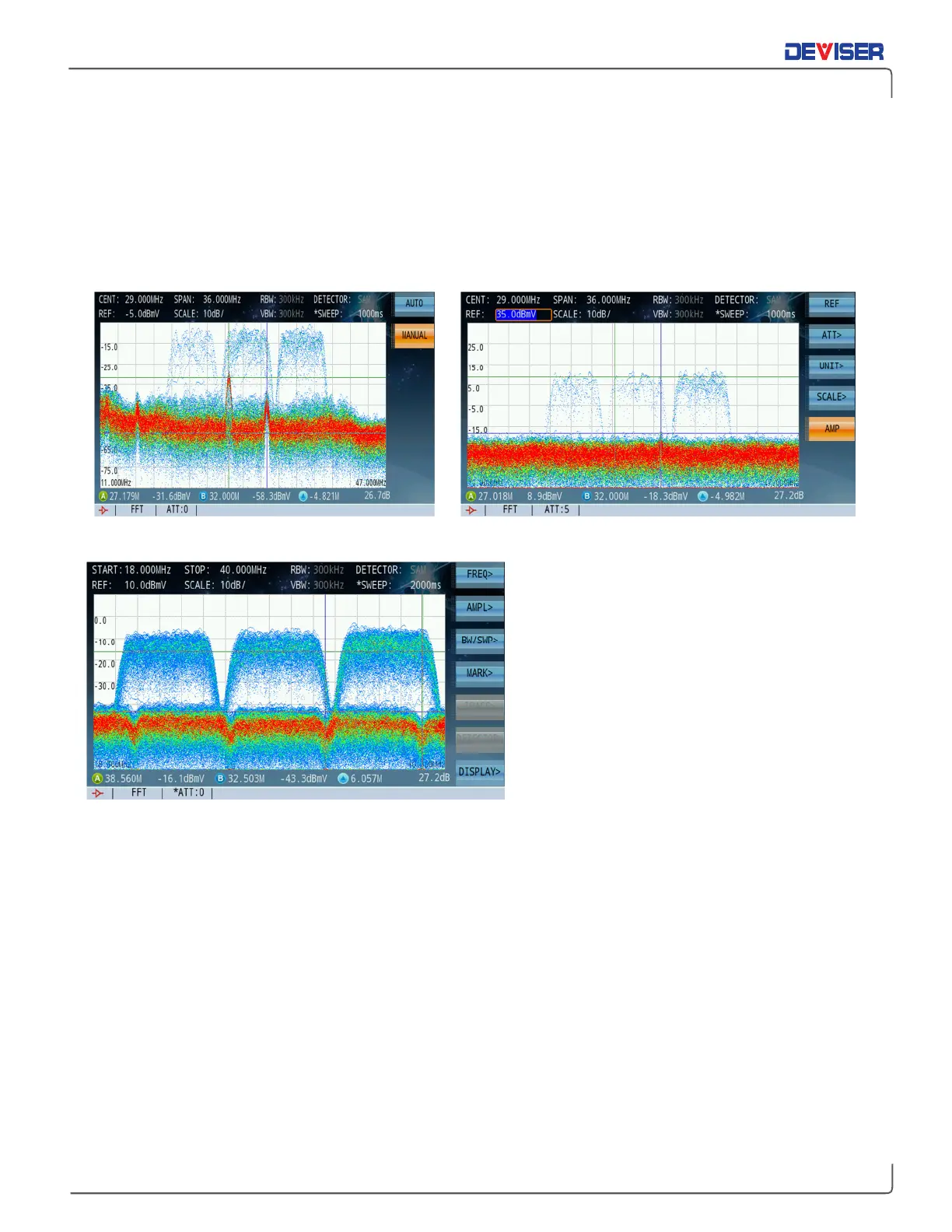
leg of a node. The figure below (left) shows the impairment at the node return test point, (without having
pulled any return pads). Although this impairment was not customer-impacting, the engineer faces an
opportunity cost in pursuing distortions at the expense of other tasks.
After chasing this impairment, it was found to have been injected through a multi-tap port – in fact, from a
non-paying connected home. After installing a filter, the impairment almost completely disappeared, as
shown (below, right).
Return path test point of an optical node Multi-tap port of a non-paying home, passed after filter was installed
However, going 100% digital does not eliminate
CPD. This capture (left) shows a rare event in
the field (Input test point, 2nd active after the
node). Here, there are 3 upstream DOCSIS 3.0
bursty transmissions at 6.4 MHz wide each – and
a clear look at, the reflected Downstream DVB-
C 6 MHz carriers sitting well below, suggesting
Digital CPD. This phenomenon is difficult to see
during field operation, simply because it is too
low for most lower-end equipment (usually SLM-
based, which offers less sensitivity than a True
Spectrum Analyzer). It might also not visibly
impact customer service.
Based on this scenario, the Deviser R&D team developed algorithms that provide consistent measurement
results – with few metrics to control in order to provide optimal results.
You can access the Spectrum Persistence analysis from the Upstream main menu. Once in the persistence
mode, you will first need to select the bandwidth of interest for your test. Depending on your location in the
network, some level adjustments – like reference level, attenuation, and activating the internal pre-amplifier
– may also be necessary. RF traffic conditions may also require speeding up or slowing down the sweep
time to extend the accumulated capture time. A sweep time of ~1000ms is ideal for capturing transient
noise under the DOCSIS carriers.
To adjust these parameters, refer to the instructions and menu map in Chapter 12: Persistence Analysis.
For further information, please contact Deviser Instruments.