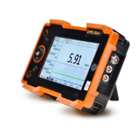
1 Introduction Important information on wall thickness measurement using the DMS Go+
1-10 Edition 4 (05/2014) DMS Go+
The following probes have been corrected individually
during the manufacturing process; the V-path correction
is stored in the probe. For some of these probes
(marked with *), this was additionally done for the oper
-
ating mode DUAL-MULTI.
Zeroing
The correct zeroing is important for the measuring accu-
racy of probes equipped with a transmitter and a receiv-
er element. A difference is made between two methods:
1 Zeroing before coupling the probe
(OFF-BLOCK zeroing)
2 Zeroing during probe coupling
(ON-BLOCK zeroing)
Zeroing before coupling the probe (OFF-BLOCK
zeroing)
After powering the DMS Go+ on, the length of the delay
line below the transmitter element is determined at reg
-
ular intervals whenever the probe is not coupled for the
wall thickness measurement. In this regard, it is import
-
ant that the coupling face of the probe is free from cou-
plant to a large extent in order to avoid any faulty mea-
surements.
This method is of advantage in cases where rough or
curved surfaces may result in a critical coupling. When
determining wall thicknesses in plastics, only probes
with zeroing before coupling should be chosen:
● DA 401 ● DA 403 ● DA 408
● DA 411 ● DA 412* ● DA 451*
● DA 453 ● DA 458 ● DA 461*
● DA 462* ● DA 455 ● DA 465
● DA 467 ● DA 469 ● FH 2 ED REM
● DA 401 ● DA 403 ● DA 408
● DA 411 ● DA 412 ● D 790
● FH 2 E ● KBA 525 ● KBA 560
● HT 400 A ● TC 560
 Loading...