Connecting a probe 3 Initial start-up
DMS Go+ Edition 4 (05/2014) 3-9
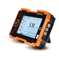
3.3 Connecting a probe
You can connect all probes recommended in chapter 2
of this manual. In addition to the probe, you need a suit
-
able probe cable for the connection between the probe
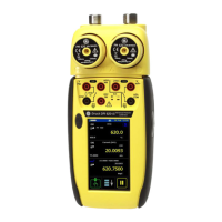
and the instrument. The probe connectors are located
on the side of the instrument.
Probes with zeroing before coupling should
not be coupled when the instrument is pow
-
ered on. The DMS Go+ tries to detect a zero
point as long as the probe is coupled.
Dual-type connectors
Most probe cables have a dual-type connector for both
connection sockets on the instrument. To prevent a
wrong connection, these connectors and the connection
sockets on the probe and on the instrument are provid
-
ed with lugs.
– Connect the probe cable with the probe.
– Connect the probe cable with the probe connections
on the side of the instrument.
Single-type connectors
If a probe is connected incorrectly, the con-
sequence would be a mismatching which
may lead to considerable power losses or
even to echo waveform distortions.
Both connector sockets are equally suitable (connected
in parallel) for connecting single-element probes so that
it does not matter which one of the two sockets is used.
When connecting a dual-element (TR) probe (having
one transmitter or pulser element and one receiver ele
-
ment) or two probes (of which one is transmitting and
the other one receiving), attention should be paid to the
correct allocation of connecting cables (please see sym
-
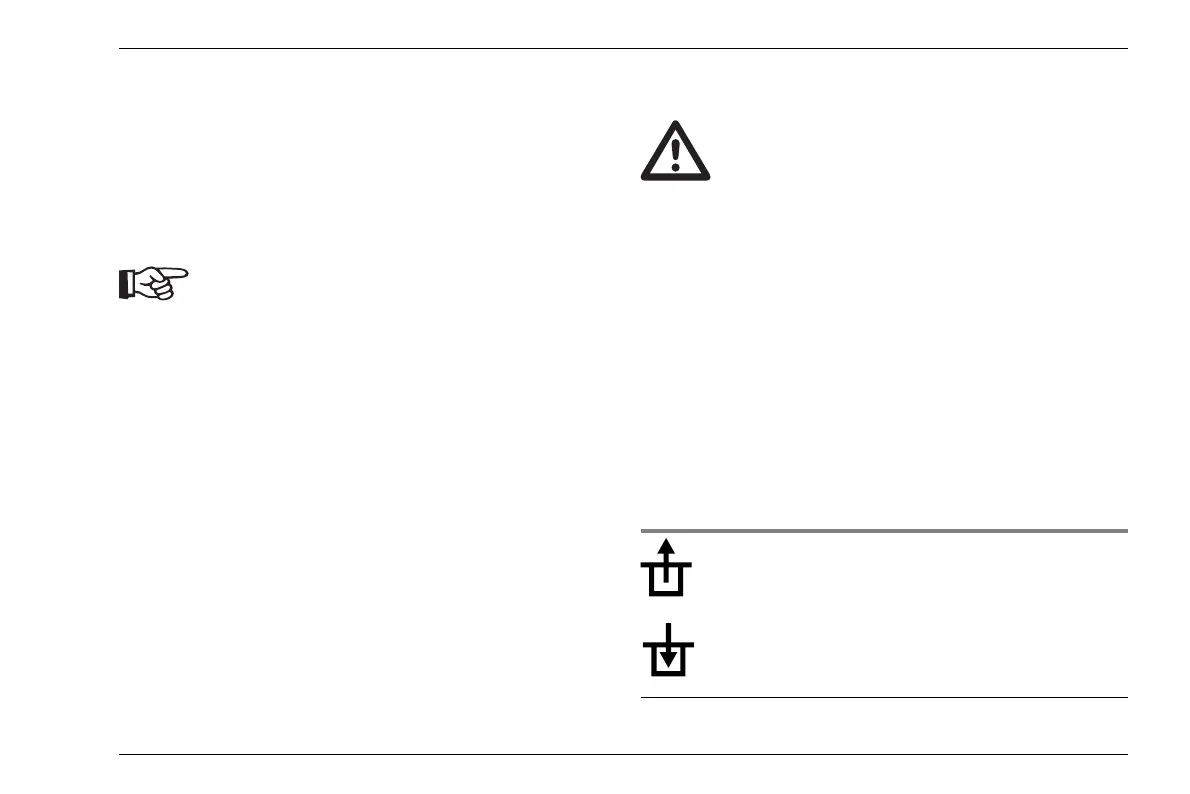
bols on the instrument):
Icon Meaning
Transmitter connection
Receiver connection