8.6 Timing Chart
118
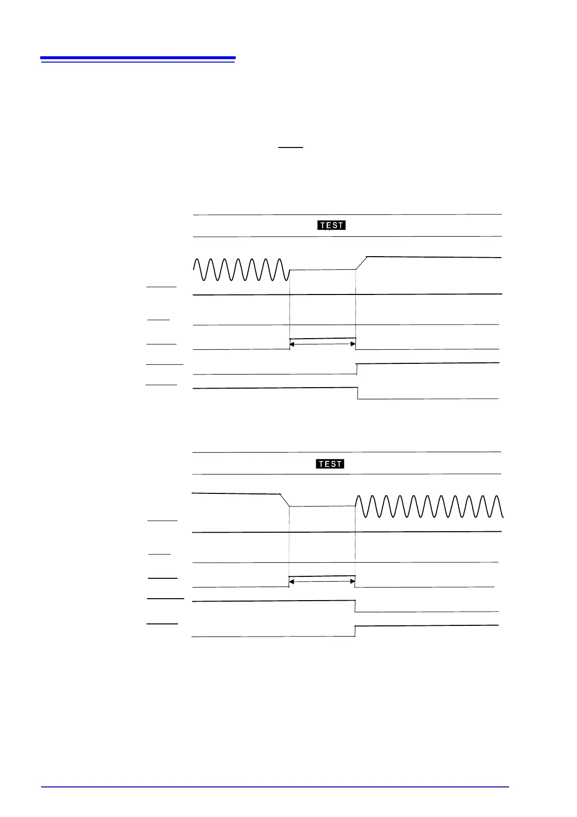
Changing during auto tests
This figure shows the switching timing chart of the instrument when it is in the
auto-test mode. In this mode, withstand-voltage and insulation-resistance tests
are conducted successively.
The instrument switches to the next test when the output-voltage value has
dropped sufficiently. The TEST
signal remains at LOW level until a series of
tests is completed.
Withstand-voltage test → Insulation-resistance test
Insulation-resistance test → Withstand-voltage test
READY
TEST
H.V.ON
W-MODE
I-MODE
140 ms max.
Voltage
Output
READY
TEST
H.V.ON
W-MODE
I-MODE
100 ms max.
Voltage
Output
 Loading...


