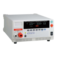
10.1 Basic Specifications
188
Decision Function
Decision method
Window comparator method (digital setting) for setting upper-limit and lower-
limit values
Decision contents UPPER FAIL : when measured current exceeds the upper-limit setting
PASS : when measured current remains between the upper- / lower
limit settings for set time
LOWER FAIL : when the measured current is below the lower-limit setting
UPPER LOWER FAIL : Test errors such as when there is no pre-set voltage
out-put
Decision process Output to the display, beeper sound, signals to EXT I/O for each decision
result
Setting range AC: 0.1 to 20.0 mA (Upper-limit value), 0.1 to 19.9 mA (Lower-limit value),
Setting resolution: 0.1 mA
Insulation resistance test portion
Rated supply 500 V/1000 V DC (positive electrode)
No load voltage 1 to 1.2 times of rated voltage
Voltage measurement Digital meter, 0 to 1000 V DC Insulation resistance, Accuracy ±30 V
Rated measurement
current
1 to 1.2 mA
Short-circuit current 4 to 5 mA (500 V), 2 to 3 mA (1000 V)
Measurement range 0.2 M to 2000 MΩ (500 V), 0.5 M to 2000 MΩ (1000 V)
Accuracy guarantee 0.5 M to 999 MΩ (500 V), 1 MΩ to 999 MΩ (1000 V): ±4%rdg
1000 M
Ω to 2000 MΩ: ±8%rdg
Measured resolution 0.01 MΩ (0.20 MΩ to 19.99 MΩ)
0.1 M
Ω (20.0 MΩ to 199.9 MΩ)
1 M
Ω (200 MΩ to 2000 MΩ)
Measurement resistance
range
2 MΩ, 20 MΩ, 200 MΩ, 2000 MΩ (500 V)
4 M
Ω, 40 MΩ, 400 MΩ, 2000 MΩ (1000 V)
Decision Function
Decision method Window comparator method (digital setting)
Decision contents UPPER FAIL : When measured resistance exceeds the upper-limit setting.
PASS : When measured resistance is within the upper-limit and
lower- limit settings.
LOWER FAIL : When the measured resistance is below the lower-limit set-
ting.
UPPER LOWER FAIL : Test errors such as when voltage is low
Decision process Output to the display, beeper sound, signals to EXT I/O for each decision
result
Setting resolution 0.01 MΩ (0.2 to 2.00 MΩ)
0.1 M
Ω (2.10 to 20.0 MΩ)
1 M
Ω (21.0 to 200 MΩ)
10 M
Ω (210 to 2000 MΩ)

 Loading...