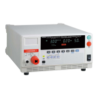
10.1 Basic Specifications
189
10
Timer Section
Setting range 0.3 to 999 s
Operation
At ON Setting : Displays the time that is counted down from the start
At OFF Setting: Displays the time that has elapsed from the start
Setting resolution 0.1 s: 0.3 to 99.9 s, 1 s: 100 to 999 s
Accuracy 0.3 to 99.9 s: ±50 ms, 100 to 999 s: ±0.5 s
Ramp timer
Setting range 0.1 to 99.9 s, The ramp-up time and ramp-down time can be set individually.
Operation Ramp-up : Using ramp-up time from initial voltage to test voltage to
increase the output voltage gradually
Ramp-down : Using ramp-down time after test time timer to decrease the out-
put voltage from pre-set voltage to 0 V
Both are displayed as time counted down from the set time.
Setting resolution 0.1 s
Accuracy ±50 ms
Delay timer (Withstand-voltage test)
Setting range 0.1 to 99.9 s
Setting resolution 0.1 s
Accuracy ±50 ms
Interface
EXT I/O (Rear panel: Each signal is insulated internally with a photocoupler)
36pin Amphenol connector
Power supply
Internal power supply Between ISO_DCV-ISO_COM:
15 V±0.5 V, 100 mA (total)
Signal level All signals Active LOW
Output signals Open collector output, (insulated with a photocoupler), All signals Active LOW
Maximum load voltage 30 V DC
Maximum output current
100 mA DC/ For 1 signal
Output saturation
voltage
1.5 V DC or less
Signal names H.V.ON : Generating voltage for output
TEST : Test in progress
PASS : PASS status at Evaluation Function setting
UFAIL : UPPER-FAIL status at Evaluation Function setting
LFAIL : LOWER-FAIL status at Evaluation Function setting
READY : Standby
I_MODE : Insulation-resistance test mode
W_MODE : Withstand-voltage test mode
W_FAIL : Withstand-voltage test failed
I_FAIL : Insulation-resistance test failed
MODE1 : Indicates current mode with MODE2 (W, I, W-I, I-W)
MODE2 : Indicates current mode with MODE1
ISO.DCV : Internal standby insulated power supply 15 V, 0.1 A
ISO.COM : Internal standby insulated power supply connections

 Loading...