SECTION 3 - CHASSIS, PLATFORM & SCISSOR ARMS
3121642 – JLG Lift – 3-65
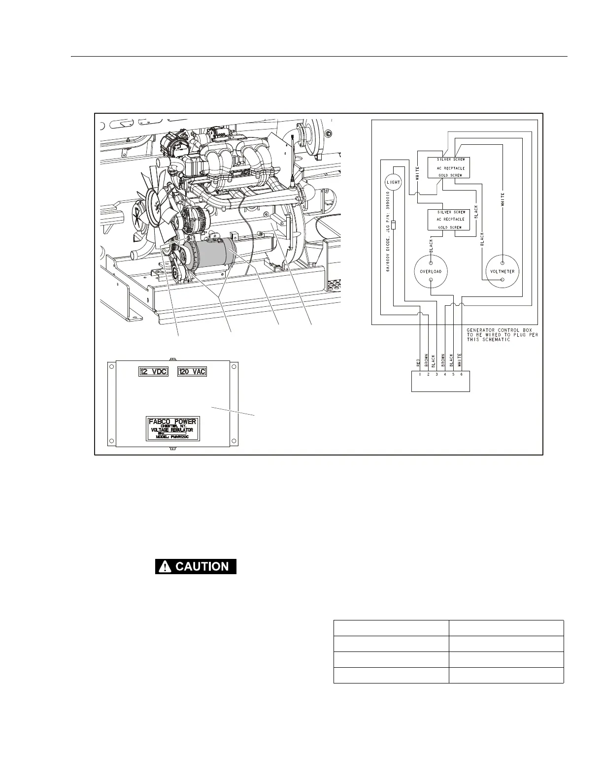
Generator
ALLOW ENGINE AND COMPONENTS TO COOL DOWN BEFORE SERVICING.
REMOVAL:
1. Disable machine operation. Disconnect and label elec-
trical wires attached to generator (1).
2. Remove the generator from the engine (2) by removing
the three bolts (3, 5) and washers (4, 5).
3. Replace belt if worn or damaged.
INSTALLATION:
1. Follow Removal Steps in reverse. Ensure belt is tight
before securing generator with the bolts.
NOTE: Apply Loctite® #242 to the bolts (3, 5).
1. Generator
2. GM Engine
3. Bolt, 5/16"-18NC x 1 1/4"
4. Washer
5. Bolt,7/16"-14NC x 1 1/4"
6. Washer
7. Voltage Regulator
Figure 3-71. Generator (GM Engine)
Table 3-12. Generator Specifications
Voltage 120V
Continuous 3.5 KW
Peak 4.5 KW
Amps Peak 37 Amps