SECTION 4 - HYDRAULICS
4-8 – JLG Lift – 3121642
17. Position the cylinder barrel in a suitable holding fixture.
EXTREME CARE SHOULD BE TAKEN WHEN INSTALLING THE CYLINDER ROD,
HEAD, AND PISTON. AVOID PULLING THE ROD OFF-CENTER, WHICH COULD
CAUSE DAMAGE TO THE PISTON AND CYLINDER BARREL SURFACES.
18. With barrel clamped securely, and while adequately sup-
porting the rod, insert the piston end into the barrel cyl-
inder. Ensure that the piston loading o-ring and seal ring
are not damaged or dislodged.
19. Continue pushing the rod into the barrel until the cylin-
der head gland can be inserted into the barrel cylinder.
20. Secure the cylinder head gland using the washer ring
and socket head bolts.
21. After the cylinder has been reassembled, the rod should
be pushed all the way in (fully retracted) prior to the
reinstallation of any holding valve or valves.
22. If applicable, install the cartridge-type holding valve and
fittings in the rod port block, using new o-rings as appli-
cable. (See Table 4-2, Holding Valve Torque Specifica-
tions).
23. Push the piston onto the rod until it abuts the spacer
end and install the attaching nut.
WHEN REBUILDING THE CYLINDERS, APPLY LOCTITE® #242 TO PISTON NUT
AND SETSCREW, THEN TORQUE PISTON NUT. REFER TO TABLE 4-1, CYLINDER
PISTON NUT TORQUE SPECIFICATIONS.
NOTE: The Steer Cylinder uses snap rings to secure piston.
24. Prior to setscrew installation spot drill rod before install-
ing the setscrew(s) which secure the piston attaching
nut to the diameter groove.
25. Remove the cylinder rod from the holding fixture.
26. Position the cylinder barrel in a suitable holding fixture.
EXTREME CARE SHOULD BE TAKEN WHEN INSTALLING THE CYLINDER ROD,
HEAD, AND PISTON. AVOID PULLING THE ROD OFF-CENTER, WHICH COULD
CAUSE DAMAGE TO THE PISTON AND CYLINDER BARREL SURFACES.
27. With barrel clamped securely, and while adequately sup-
porting the rod, insert the piston end into the barrel cyl-
inder. Ensure that the piston loading o-ring and seal ring
are not damaged or dislodged.
28. Continue pushing the rod into the barrel until the cylin-
der head gland can be inserted into the barrel cylinder.
29. If applicable, secure the cylinder head retainer using a
suitable chain wrench.
30. After the cylinder has been reassembled, the rod should
be pushed all the way in (fully retracted) prior to the
reinstallation of any holding valve or valves.
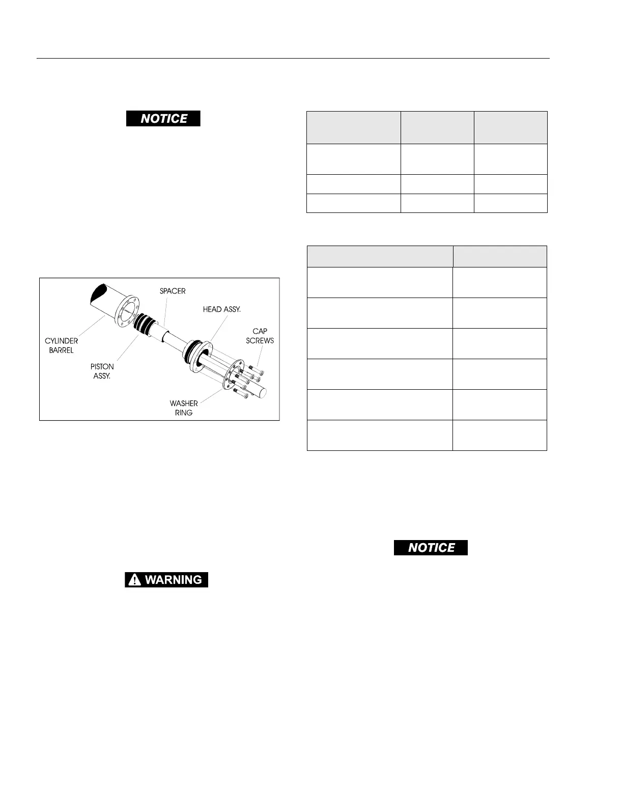
Figure 4-14. Rod Assembly Installation
Table 4-1. Cylinder Piston Nut Torque Specifications
Description Nut Torque Value
Setscrew torque
Value
Lift Cylinder
400 lb-ft
(542 Nm)
100 in.lbs.
(12 Nm)
Lockout Cylinder N/A N/A
Steer Cylinder N/A N/A
Table 4-2. Holding Valve Torque Specifications
Description Torque Value
Sun - 7/8 hex M20 x 1.5 thds
30 - 35 lb-ft
(41 - 48 Nm)
Sun - 1-1/8 hex 1 - 14 UNS thds
45 - 50 lb-ft
(61 - 68 Nm)
Sun - 1-1/4 hex M36 x 2 thds
150 - 153 lb-ft
(204 - 207 Nm)
Racine - 1-1/8 hex 1-1/16 - 12 thds
50 - 55 lb-ft
(68 - 75 Nm)
Racine - 1-3/8 hex 1-3/16 - 12 thds
75 - 80 lb-ft
(102 - 109 Nm)
Racine - 1-7/8 hex 1-5/8 - 12 thds
100 - 110 lb-ft
(136 - 149 Nm)