SECTION 3 - CHASSIS, PLATFORM & SCISSOR ARMS
3121642 – JLG Lift – 3-47
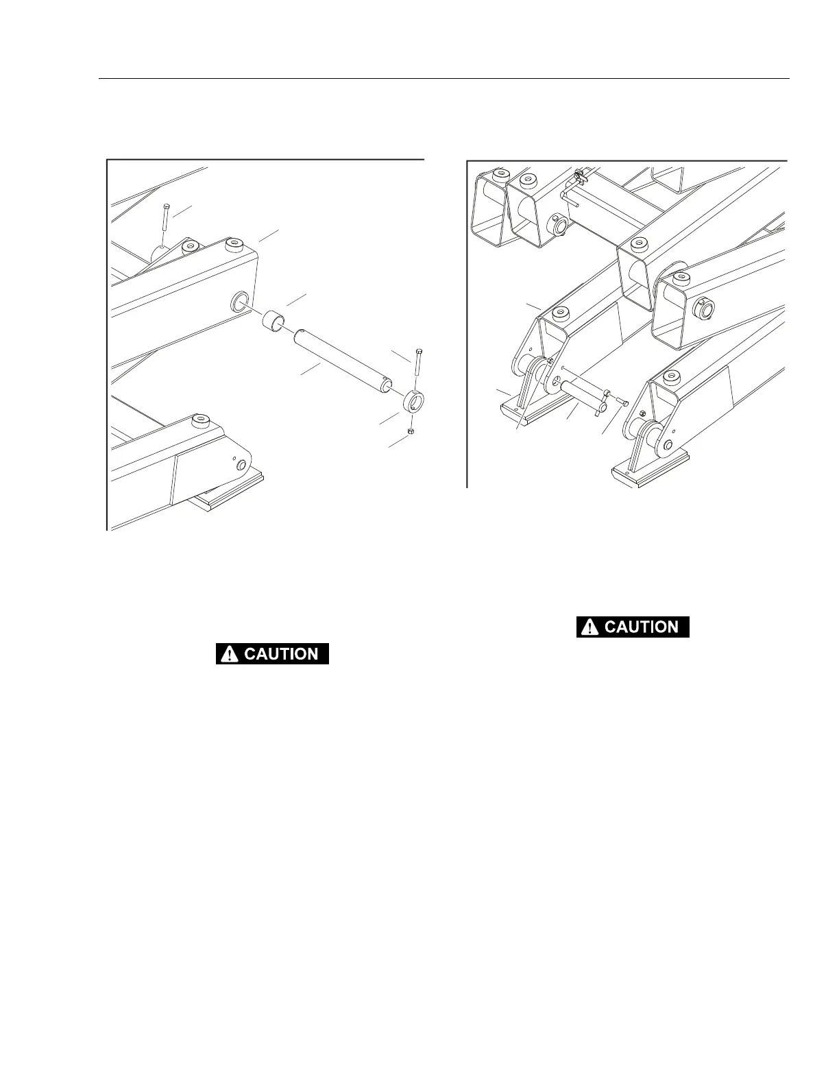
Scissor Arms Removal
NEVER WORK UNDER ELEVATED SCISSOR ARMS WITHOUT FIRST PROPERLY
BRACING/BLOCKING SCISSOR ARM ASSEMBLY.
NOTE: Scissor arms can be removed individually or as an entire
assembly.
ARM REMOVAL:
1. Remove platform (refer to Figure 3-37.) and lift cylinder
(refer to Figure 3-41.).
2. Disconnect, cap and label all hydraulic hoses and wiring
attached to scissor arms.
3. Support the scissor arm(s) being removed.
4. Remove the pin (2) from the scissor arm (1) by removing
the two bolts (3), nuts (4) and collar (5).
5. Push pin and bearing (6) out from scissor arms.
6. Repeat at each connecting pin.
INSTALLATION:
1. Follow Removal Steps in reverse.
Scissor Arm Assembly Removal
NEVER WORK UNDER ELEVATED SCISSOR ARMS WITHOUT FIRST PROPERLY
BRACING/BLOCKING SCISSOR ARM ASSEMBLY.
REMOVAL:
NOTE: Applies to all four corners.
1. Remove platform (refer to Figure 3-37., Platform
Removal).
2. Disconnect, cap and label all hydraulic hoses and wiring
attached to scissor arms and lift cylinder.
3. Support the scissor arm assembly with appropriate lift-
ing straps and overhead crane.
4. Disconnect the scissor arm assembly from the four slid-
ers (2) by removing the bolts (4) and nuts (5)
5. Push pins (3) out.
6. Carefully lift arm assembly up and away from chassis.
INSTALLATION:
Follow Removal Steps in reverse.
1. Scissor Arm
2. Pin
3. Bolt, 3/8"-16NC x 3"
4. Nut
5. Collar
6. Bearing
Figure 3-42. Scissor Arms Removal
1. Scissor Arm
2. Slider
3. Pin
4. Bolt, 3/8"-16NC x 1 1/4"
5. Nut
Figure 3-43. Scissor Assembly Removal - Chassis Connec-
tion