SECTION 3 - CHASSIS, PLATFORM & SCISSOR ARMS
3-74 – JLG Lift – 3121642
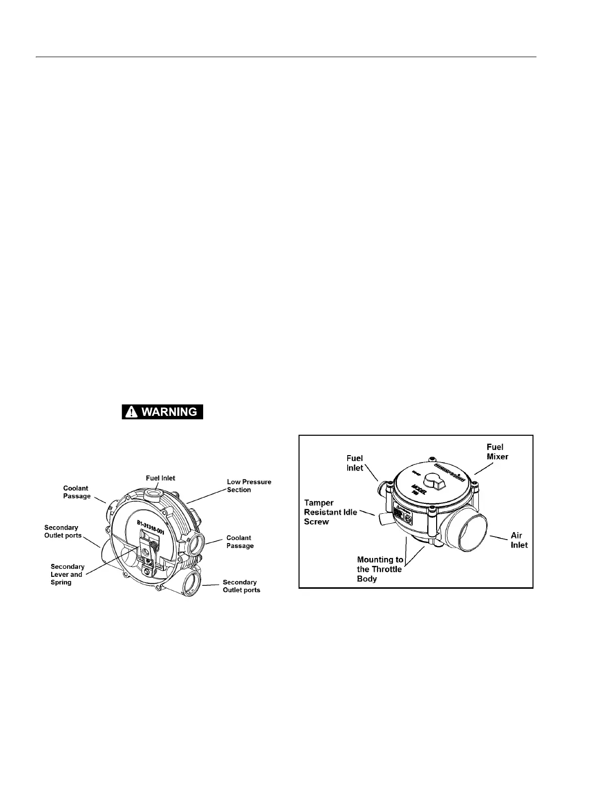
Low Pressure Regulator (LPR)
The LPR is a combination vaporizer, pressure regulating
device. The LPR is a negative pressure, two stage regulator that
is normally closed when the engine is not running. When the
engine is cranking or running, a partial vacuum is created in
the fuel line which connects the regulator to the mixer. This
partial vacuum opens the regulator permitting fuel to flow to
the mixer.
Propane fuel enters the primary port of the LPR and passes
through the primary jet and into the primary/ exchanger
chamber. As the propane passes through the heat exchanger,
the fuel expands and creates pressure inside the chamber. The
pressure rises as the fuel expands. When the pressure rises
above 1.5 psi (0.103 bar), sufficient pressure is exerted on the
primary diaphragm to cause the diaphragm plate to pivot and
press against the primary valve pin, thus closing off the flow of
fuel. This action causes the flow of fuel into the regulator to be
regulated.
When the engine is cranking, sufficient vacuum will be intro-
duced into the secondary chamber from the mixer drawing
the secondary diaphragm down onto the spring loaded lever
and opening the secondary valve allowing vaporized fuel to
pass to the mixer. This mechanical action, in conjunction with
the EPR reactions, causes the downward action on the second-
ary lever, causing it to open wider allowing more fuel to flow
to the mixer.
THE VOICE COIL SECTION OF THE EPR ASSEMBLY IS AN EMISSIONS CONTROL
DEVICE AND CANNOT BE REBUILT. IF THE COIL ASSEMBLY FAILS TO OPERATE
PROPERLY, REPLACE IT WITH AN OEM REPLACEMENT PART ONLY.
Air Fuel Mixer
The air valve mixer is an air-fuel metering device and is com-
pletely self-contained. The mixer is an air valve design, utiliz-
ing a relatively constant pressure drop to draw fuel into the
mixer from cranking to full load. The mixer is mounted in the
air stream ahead of the throttle control device.
When the engine begins to crank, (it draws in air with the air
valve covering the inlet) negative pressure begins to build.
This negative pressure signal is communicated to the top of
the air valve chamber through 4 vacuum ports in the air valve
assembly. A pressure/force imbalance begins to build across
the air valve diaphragm between the air valve vacuum cham-
ber and the atmospheric pressure below the diaphragm. The
air valve vacuum spring is calibrated to generate from 4.0
inches (101.6 mm) of water column at start to as high as 14.0
inches (355.60 mm) of water column at full throttle. The vac-
uum being created is referred to as Air Valve Vacuum (AVV). As
the air valve vacuum reaches 4.0 inches (101.6 mm) of water
column, the air valve begins to lift against the air valve spring.
The amount of AVV generated is a direct result of the throttle
position. At low engine speed, the air valve vacuum is low and
the air valve position is low, thus creating a small venturi for
the fuel to flow. As the engine speed increases, the AVV
increases and the air valve is lifted higher, thus creating a
much larger venturi. This AVV is communicated from the mixer
venture to the LPR secondary chamber via the low pressure
fuel supply hose. As the AVV increases in the secondary cham-
ber, the secondary diaphragm is drawn further down, forcing
the secondary valve lever to open wider.
Figure 3-81. Low Pressure Regulators
Figure 3-82. Air Fuel Mixer