SECTION 3 - CHASSIS, PLATFORM & SCISSOR ARMS
3121642 – JLG Lift – 3-41
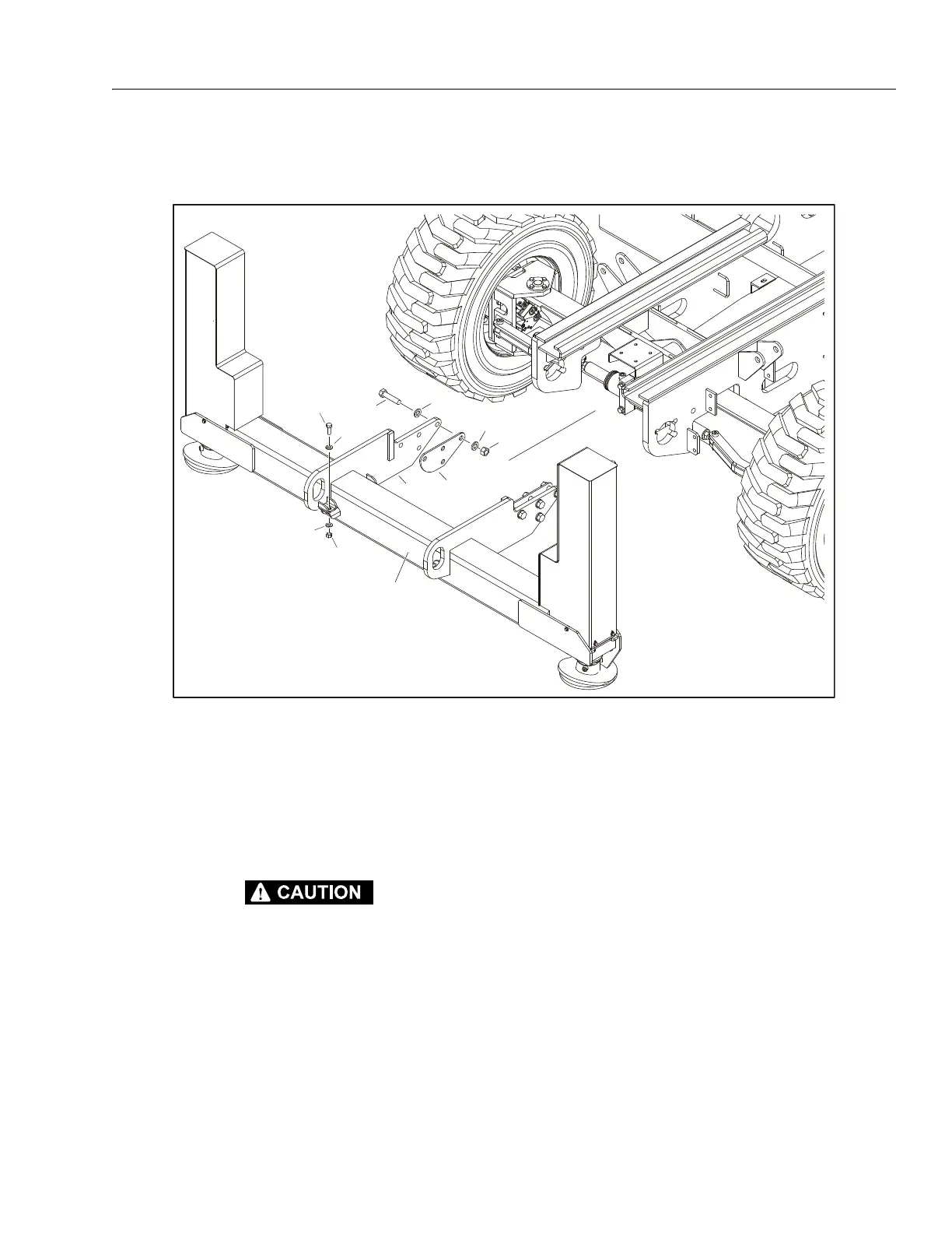
Assembly Removal
NOTE: Applies to both front and rear of machine.
REMOVAL:
SUPPORT THE LEVELING JACKS ASSEMBLY BEFORE ATTEMPTING ANY
REMOVAL AND/OR ASSEMBLY PROCEDURES.
1. Disable machine operation and block all wheels.
2. Remove covers from leveling jack cylinders (refer to Fig-
ure 3-35., Leveling Jack Cylinder Removal).
3. Disconnect, cap and label hydraulic lines connected to
leveling jack cylinders. Disconnect and label all electrical
wiring attached to cylinder and switches.
4. Remove the four bolts (2), nuts (3) and washers (4).
5. Carefully lower assembly from the supports (9).
6. Supports can be removed from chassis by removing the
four bolts (5), nuts (6) and washers (7).
INSTALLATION:
1. Follow Removal Steps in reverse.
NOTE: Torque bolts (5) to 280 lb-ft (379.6 Nm).
2. Uncap and reconnect hydraulic lines and electrical wires
to cylinders and switches.
3. Operate leveling jacks to ensure proper operation.
1. Leveling Jacks Assembly
2. Bolt, 1/2"-13NC x 1 3/8"
3. Nut
4. Washer
5. Bolt, 3/4" - 10NC x 3 1/4"
6. Nut
7. Washer
8. Plate
9. Support
Figure 3-36. Leveling Jacks Assembly