SECTION 3 - CHASSIS, PLATFORM & SCISSOR ARMS
3-36 – JLG Lift – 3121642
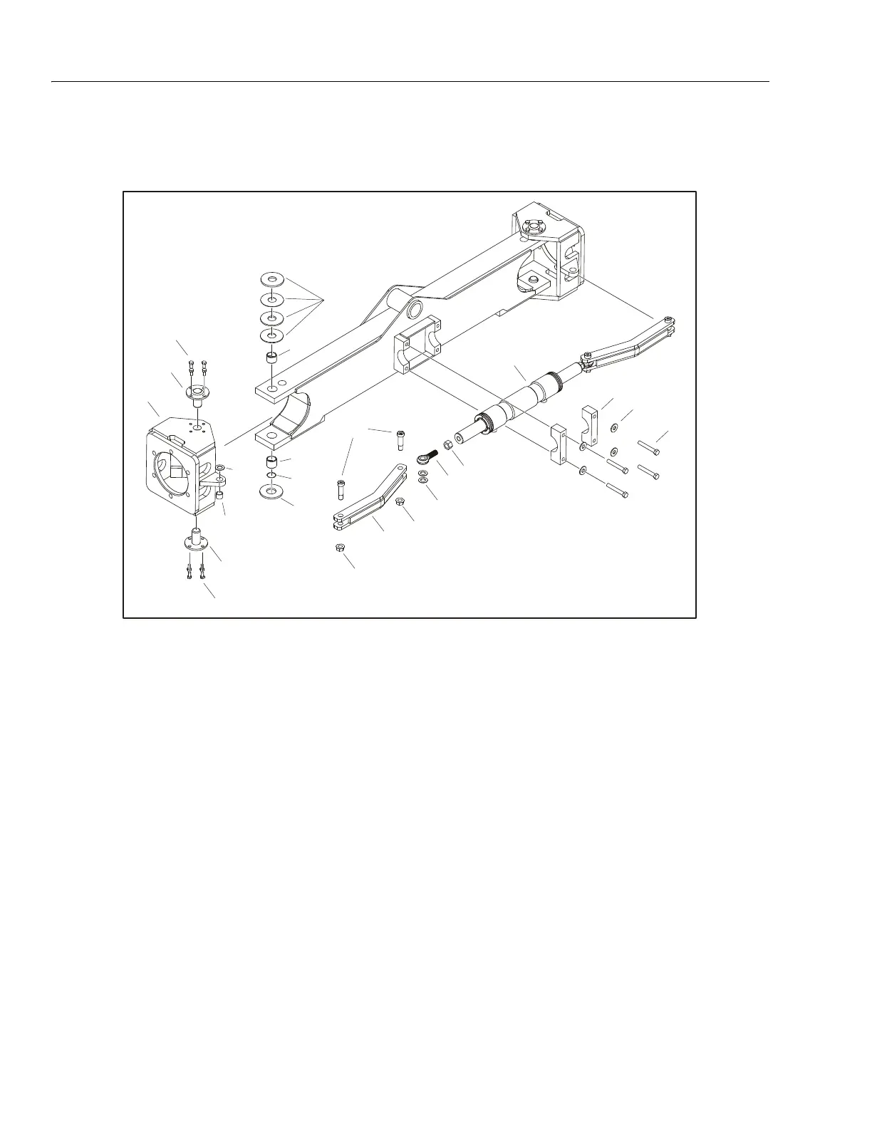
3.5 FRONT AXLE
Steering Assembly
STEER CYLINDER REMOVAL:
1. Disable machine operation and block all wheels. Discon-
nect, cap and label all hydraulic lines and electrical wir-
ing on steer cylinder (1).
2. Support steer cylinder. Remove the screws (2), nuts (3)
and thrust washers (4) connecting cylinder to tie rod (7).
Remove end bearing rod (8) and nut (9) from cylinder.
3. Remove 4 bolts (10) and washers (11) connecting cylin-
der to axle. Carefully remove cylinder.
Spindle Removal:
1. Remove wheel and drive assembly prior to spindle (13)
removal (refer to Figure 3-1., Drive Assembly (Bosch
Rexroth )).
2. Support spindle. Disconnect tie rod (7) from spindle by
removing bolt (2), nut (3) and thrust washer (5).
3. Remove spindle from axle by removing 8 bolts (14), 2
kingpins (15), 5 thrust washers (16, 18) and o-ring (19).
ASSEMBLY:
1. When assembling steer cylinder and spindle, follow
Removal Steps in reverse.
NOTE: Apply Loctite® #242 to bolts (10, 14) and nut (3).
Apply bearing grease lube to the grooves on the bearings
(17, 20) before installing.
Ensure thrust washer (5) is between tie rod (7) and top side
of spindle (13).
Refer to Figure 4-28., Steer Cylinder for steer cylinder break-
down.
1. Steer Cylinder
2. Screw, 3/4"D x 1 3/4"
3. Nut
4. Thrust Washer
5. Thrust Washer
6. Bearing
7. Tie Rod
8. End Bearing Rod
9. Nut
10. Bolt, 1/2"-13 x 3 1/2"
11. Washer
12. Cylinder Block
13. Spindle
14. Bolt, 3/8"-16 x 3/4"
15. Kingpin
16. Thrust Washer
17. Bearing
18. Thrust Washer
19. O-ring
20. Bearing
Figure 3-28. Steering Assembly