SECTION 3 - CHASSIS, PLATFORM & SCISSOR ARMS
3121642 – JLG Lift – 3-75
Electronic Throttle Control (ETC)
Engine speed and load control is maintained by an ETC device.
Speed and load control are determined by the ECM. Defaults
programmed into the ECM software and throttle position sen-
sors allow the ECM to maintain safe operating control over the
engine. The Electronic Throttle Control device, or "throttle
body assembly", is connected to the intake manifold of the
engine. The ETC device utilizes an electric motor connected to
the throttle shaft. When the engine is running, electrical sig-
nals are sent from the equipment controls to the engine ECM
when the operator depresses an equipment function switch.
The ECM then sends an electrical signal to the motor on the
electronic throttle control to increase or decrease the angle of
the throttle blade, thus increasing or decreasing the air/fuel
flow to the engine.
The electronic throttle control device also incorporates two
internal Throttle Position Sensors (TPS) which provide output
signals to the ECM as to the location of the throttle shaft and
blade. The TPS information is used by the ECM to correct
speed and load control as well as emission control.
Engine Control Module (ECM)
To obtain maximum effect from the catalyst and accurate con-
trol of the air fuel ratio, the emission certified engine is
equipped with an onboard computer or ECM. The ECM is a 32
bit controller which receives input data from sensors fitted to
the engine and fuel system and then outputs various signals
to control engine operation.
One specific function of the controller is to maintain "closed
loop fuel control". Closed loop fuel control is accomplished
when the exhaust gas oxygen sensor (HEGO) mounted in the
exhaust system sends a voltage signal to the controller. The
controller then calculates any correction that may need to be
made to the air fuel ratio. The controller then outputs signals
to the EPR to correct the amount of fuel being supplied to the
mixer. At the same time, the ECM may correct the throttle
blade position to correct the speed and load of the engine.
The controller also performs diagnostic functions on the fuel
system and notifies the operator of malfunctions by turning
on a Malfunction Indicator Light (MIL) mounted in the Ground
Control Station and the Platform Control Station. Malfunctions
in the system are identified by a Diagnostic Code number. In
addition to notifying the operator of the malfunction in the
system, the controller also stores the information about the
malfunction in its memory.
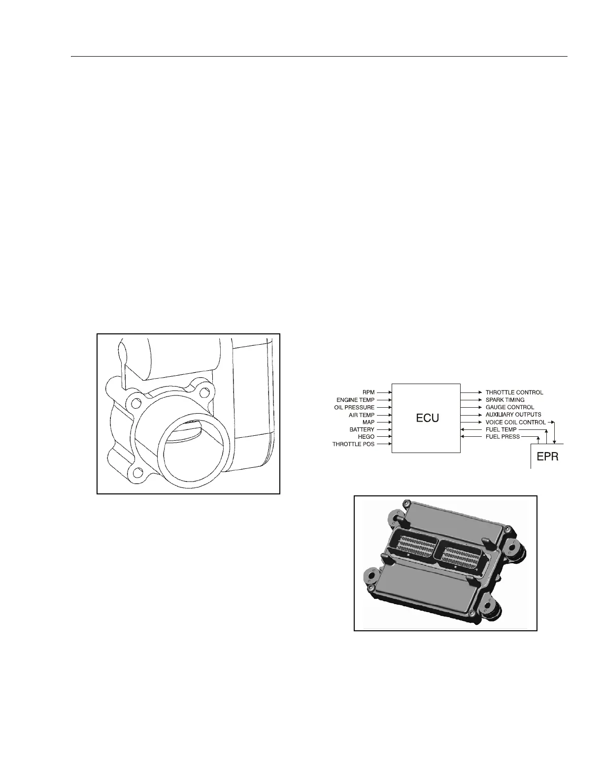
Figure 3-83. ETC throttle control device
Figure 3-84. LPG Engine Control Unit (ECM)
Figure 3-85. ECM Assembly