SECTION 4 - HYDRAULICS
3121642 – JLG Lift – 4-27
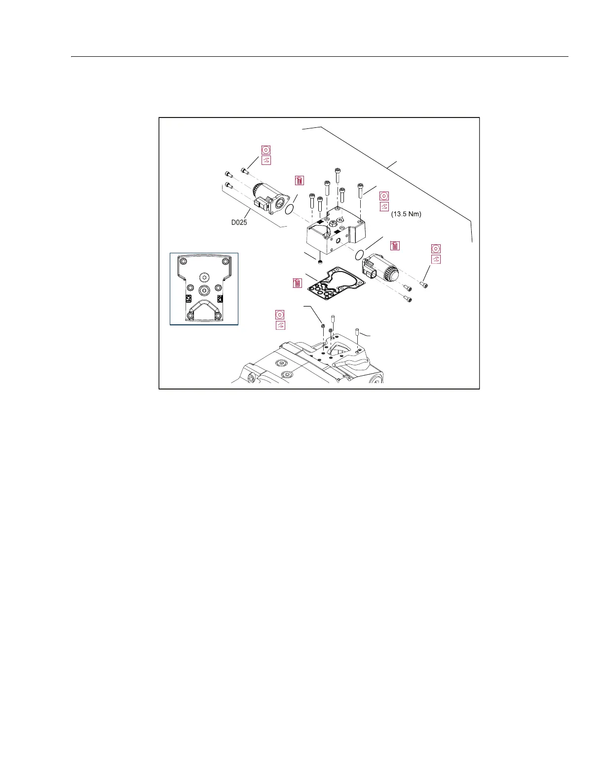
Electric Control Module
REMOVAL:
1. Using a 5 mm internal hex wrench, remove the six cap
screws (D250).
2. Remove the control module and gasket (D150). Discard
the gasket.
3. If necessary, remove orifices (F100) using a 3 mm inter-
nal hex wrench. Tag and number them for reinstallation.
INSPECTION:
4. Inspect the machined surfaces on the control and top of
the pump. If you find any nicks or scratches, replace the
component.
REASSEMBLY:
NOTE: Ensure you install dowel pins (D300) in housing before
installing control.
5. Install a new gasket (D150).
6. If you removed screen (D084), install a new one. Install
with the mesh facing outward (see drawing).
7. If previously removed, install orifices (F100) using a 3
mm internal hex wrench. Torque to 1.8 lb-ft (2.5 Nm).
8. Install the control module and six cap screws (D250).
9. Using a 5 mm internal hex wrench, torque the cap
screws (D250) to 10 lb-ft (13.5 Nm).
Control Solenoids
REMOVAL:
1. Disconnect electrical connection and remove the three
cap screws (D050) using a 4 mm internal hex wrench.
2. Remove the solenoid (D025) and O-ring (D025A). Dis-
card the O-ring.
3. If necessary, remove the coil using a 12 point 26 mm
socket.
INSPECTION:
4. Inspect the machined surface on the control. If you find
any nicks or scratches, replace the component.
REASSEMBLY:
5. Lubricate new O-ring (D025A) using petroleum jelly and
install.
6. Install solenoid with three cap screws (D050) using a 4
mm internal hex wrench. Torque screws to 5 Nm (4 lb-ft).
7. Install coil using a 12 point 26 mm socket. Torque coil
nut to 3.7 lb-ft (5 Nm).
D1
D025A
D025A
D150
5 mm
10 ft.lbs.
D250
D050 (3X)
D084
4 ft.lbs. (5 Nm)
4 mm
4 ft.lbs.
(5 Nm)
4 mm
F100 (2X)
1.8 ft.lbs.
()2.5 Nm
3 mm
2
3
4
56
1
Torque sequence