SECTION 3 - CHASSIS, PLATFORM & SCISSOR ARMS
3-76 – JLG Lift – 3121642
Heated Exhaust Gas Oxygen Sensor (HEGO)
There are two Heated Exhaust Gas Oxygen Sensors (HEGO).
The first HEGO is mounted in the exhaust system downstream
of the engine. It is used to measure the amount of oxygen
present in the exhaust stream and communicate that to the
ECM via an electrical signal. The amount of oxygen present in
the exhaust stream indicates whether the fuel/air ratio is too
rich or too lean. If the HEGO sensor signal indicates that the
exhaust stream is too rich, the ECM will decrease or lean the
fuel mixture during engine operation. If the mixture is too
lean, the ECM will richen the mixture. The ECM continuously
monitors the HEGO sensor output. If a rich or lean condition is
present for an extended period of time and the ECM cannot
correct the condition, the ECM will set a diagnostic code and
turn on the MIL light in the control box.
The second HEGO is mounted in the exhaust system after the
muffler. It measures the amount of oxygen in the exhaust sys-
tem after the catalyst treatment has been completed in the
muffler. If the ECM detects that the catalytic action in the muf-
fler is not sufficient and fuel correction cannot correct the mal-
function, the MIL light is illuminated in the control box and a
DTC code will be stored in the computer.
THE HEATED EXHAUST GAS OXYGEN SENSOR IS AN EMISSION CONTROL
DEVICE. IF THE HEGO FAILS TO OPERATE, REPLACE IT WITH AN OEM REPLACE-
MENT PART. THE HEGO SENSOR IS SENSITIVE TO SILICONE OR SILICONE
BASED PRODUCTS AND CAN BECOME CONTAMINATED. AVOID USING SILICONE
SEALERS OR HOSES TREATED WITH SILICONE LUBRICANTS IN THE AIR
STREAM OR FUEL LINES.
Gasoline Multi Point Fuel Injection System (MPFI)
The primary components of the Gasoline Multi Point Fuel
Injection (MPFI) fuel system are the fuel tank, electric fuel
pump, fuel pressure and temperature sensor manifold, fuel fil-
ter and fuel rail.
Gasoline Fuel Pump
The Gasoline is stored as a liquid in the fuel tank and is drawn
into the fuel system by an electric fuel pump. The fuel pump
will receive a signal from the ECM to prime the fuel system for
approximately 2 seconds prior to start. Priming of the fuel sys-
tem provides for a quicker start when the engine begins to
crank.
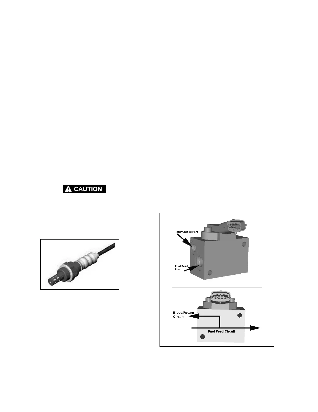
Gasoline Pressure And Temperature Sensor
Manifold
This engine is equipped with a fuel injector rail that does not
have a pressure regulator or a return circuit to the fuel tank.
Fuel pressure for this engine is regulated by the engine’s ECM.
The ECM receives fuel pressure and temperature feedback
from the gasoline fuel sensor manifold and uses this informa-
tion to control the ground side of the fuel pump. Fuel pressure
is regulated by the ECM pulse width modulating (PWM) the
fuel pump. The fuel pressure and temperature sensor manifold
has a return, or "bleed", circuit that connects back to the fuel
tank. This circuit is used to bleed off any vapor that develops in
the line and return a small amount of fuel to the tank. The fuel
comes from the fuel tank and passes through the fuel pump.
Fuel exits the fuel pump, passes through the filter and then
enters the fuel pressure and temperature manifold assembly.
Fuel flows through the feed circuit and is delivered to the fuel
injector rail. Fuel that enters the bleed circuits through the
bypass valve in the manifold is returned to the fuel tank.
Fuel Filter
Figure 3-86. Heated Exhaust Gas Oxygen Sensor (HEGO)
Figure 3-87. Gasoline Fuel Pressure and Temperature
Manifold Assembly