SECTION 4 - HYDRAULICS
4-28 – JLG Lift – 3121642
8. Reconnect electrical connections and test the pump for
proper operation.
Shaft Seal, Roller Bearing & Shaft Replacement
NOTE: The shaft assembly is serviceable without disassembling
the pump. Orient the pump on the work surface so the
shaft is pointing to the side.
REMOVAL:
1. Unwind the spiral ring (J300) from the housing to
release the shaft/seal/bearing subassembly.
2. Pry on the lip of the seal carrier (J275) to dislodge it from
the pump. Remove the seal carrier. Remove and discard
O-ring (J260). Press the seal (J250) out of the carrier and
discard.
3. Pull the shaft (J100) with bearing (J150) out of the
pump. If necessary, tap lightly on the shaft to dislodge it
from the cylinder block.
4. Remove the retaining ring (J200) using retaining ring
pliers. Press the bearing off the shaft.
INSPECTION:
5. Inspect the shaft journals for wear, scratching, and pits.
Check the splines for fretting; replace if damaged.
Rotate the bearing, if it does not rotate smoothly,
replace it.
REASSEMBLY:
6. Press the bearing (J150) onto the shaft (J100) and
replace the retaining ring (J200). Ensure the retaining
ring diameter is less than 1.53 in (38.84 mm) when
installed on the shaft.
7. Install the shaft/bearing assembly into the pump.
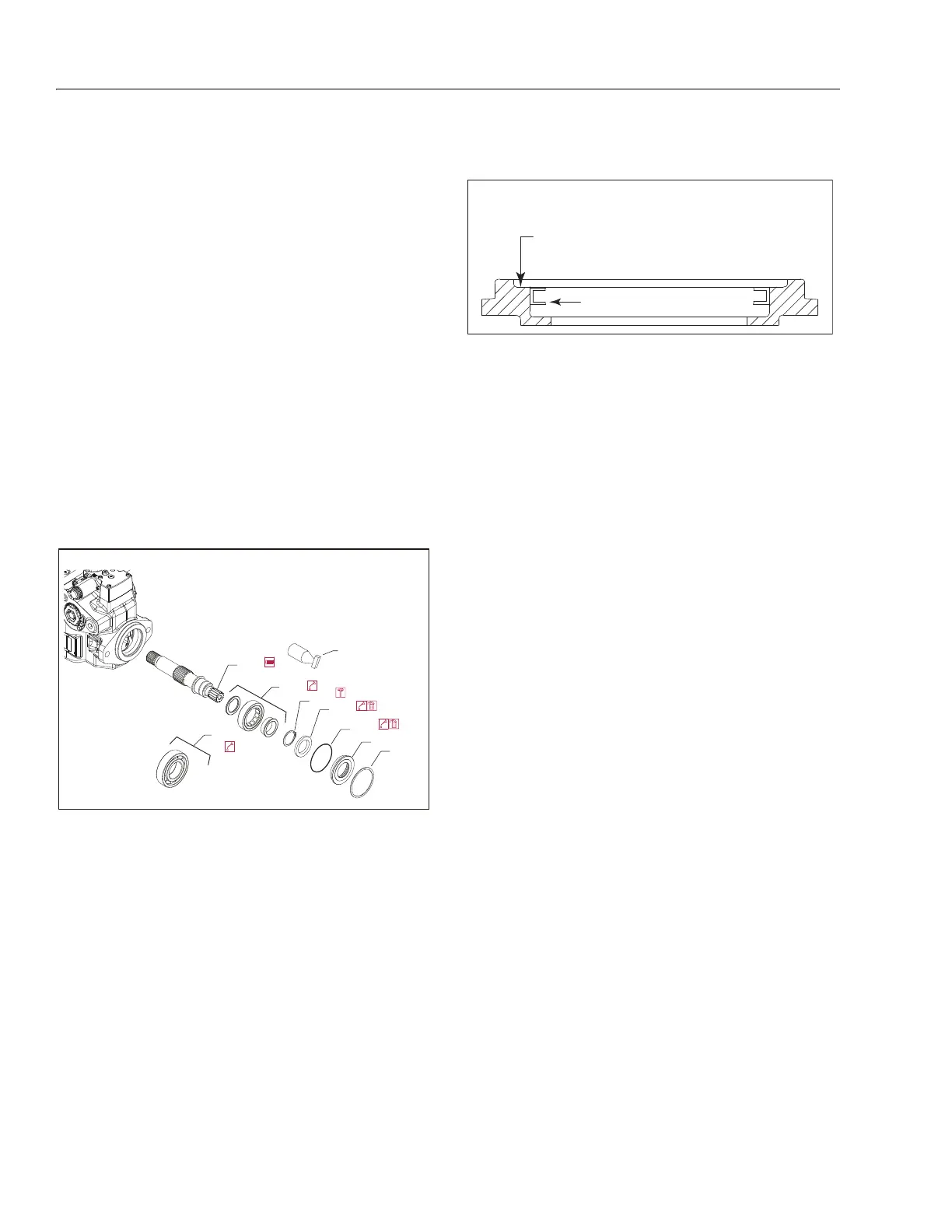
8. Lubricate and install a new O-ring (J260) onto seal car-
rier (J275). Press a new seal (J250) into the seal carrier.
Press the seal until it is flush within 0.005 in (+0.12mm )
or 0.0028 in (-0.72 mm) of the inside lip of the carrier: see
illustration.
9. Cover the shaft with a protective sleeve while installing
the seal carrier. Hand press the seal carrier into the hous-
ing. Ensure the seal carrier clears the spiral ring groove
in the housing. Remove the protective sleeve.
10. Wind the spiral ring into the housing. Ensure the inside
diameter of the spiral ring is greater than 2.677 in (68
mm) after installation.
Charge Pump
If the pump has an auxiliary pump attached, remove the auxil-
iary pump and connecting shaft before removing the auxiliary
pad.
REMOVAL:
1. Position pump so end cover or auxiliary pad is on top.
2. If necessary, remove auxiliary pump (not shown), or
shipping cover (K300) and pad seal (K250) as shown on
following page.
3. Remove end cover/auxiliary pad screws (K400) using a
10 mm internal hex wrench.
NOTE: Alignment pins (G450) are in end cover. They may dislodge
during disassembly.
4. Remove and discard gasket (K150).
5. Remove thrust washer (K500). Note thrust washer orien-
tation.
6. Use a small hook to remove pressure balance plate
(S200) and seal (S300). Note plate orientation. Discard
seal.
7. Remove coupling (K200). Use a small hook if necessary.
8. Remove the charge pump outer ring (S150), and gearset
(S100).
9. Remove valve plate (S250) with seal (S300). Discard seal
INSPECTION:
10. Inspect the components for wear, scratches or pitting.
Carefully inspect the valve and pressure-balance plates.
Scratches on these components will cause a loss of
Shaft assembly
J150
J100
J200
J250
J260
J275
J300
J150
Protective
sleeve
Seal
Press flush to this surface
0.005 in +0.12 mm) 0.028 in -0.72 mm) ( / (
Positioning seal in seal carrier