SECTION 3 - CHASSIS, PLATFORM & SCISSOR ARMS
3121642 – JLG Lift – 3-73
3.17 GM ENGINE DUAL FUEL SYSTEM
The Dual Fuel system allows the operator to operate the vehi-
cle on either gasoline or LPG by positioning a selector switch
on the platform control station. When the operator places the
selector switch in the gasoline mode, the gasoline fuel pump
is energized. While in the gasoline mode, the LPG fuel lock-off
is isolated and will not energize. In addition, the gasoline injec-
tor circuit is enabled and injector pulses are provided to each
injector and the ECM calibration for gasoline is also enabled.
When the operator selects the LPG mode, the Low Pressure
LPG lock-off is energized and fuel from the LPG tank flows to
the Electronic Pressure Regulator (EPR). The EPR receives an
electronic signal to position the secondary lever for the start or
run positions and when the engine begins to crank, the mixer
air valve will rise and fuel will begin flowing to engine. During
this mode, the gasoline fuel pump is isolated and will not be
activated. The primary components of the gasoline dual fuel
system are the gasoline tank, electric fuel pump and filter, fuel
supply line, injector rail and injectors and the fuel pressure
regulator. The primary components of the LPG dual fuel sys-
tem are the LPG fuel tank, in-fuel filter, LPG Low Pressure lock-
off, EPR and the fuel mixer module. The LPG fuel system oper-
ates at pressures which range from 14.0 inches (355.60 mm) of
water column up to 312 psi (21.5 bar).
Components which are shared by both systems include the
Electronic Throttle Control and the ECM. The ECM contains a
dual calibration; one controls the gasoline fuel system during
gasoline operation and one controls the LPG fuel system dur-
ing LPG operation.
Fuel Filter
Propane fuel like all other motor fuels is subject to contamina-
tion from outside sources. Refueling of the equipment’s tank
and removal of the tank from the equipment can inadver-
tently introduce dirt and other foreign matter into the fuel sys-
tem. It is therefore necessary to filter the fuel prior to entering
the fuel system components downstream of the tank. An
inline fuel filter has been installed in the fuel system to remove
the dirt and foreign matter from the fuel. The inline filter is
replaceable as a unit only. Maintenance of the filter is critical to
proper operation of the fuel system and should be replaced as
specified in Section 1. In severe operating conditions, more
frequent replacement of the filter may be necessary.
Electric Lock Off
The Electric Lock Off device is an integrated assembly. When
energized, the solenoid opens the valve and allows the Pro-
pane fuel to flow through the device. The valve opens during
cranking and run cycles of the engine. The lock off supply volt-
age is controlled by the engine control module (ECM).
Electronic Pressure Regulator Assembly
The EPR assembly is a combination Low Pressure Regulator
and a Voice Coil Assembly. The Voice Coil is an electronic actu-
ator which is controlled by an internal microprocessor. The
microprocessor provides output data to the ECM and receives
input data over a CAN BUS connection. The internal micropro-
cessor receives electrical signals from the Fuel Pressure Sensor
(FPS) and the Fuel Temperature Pressure FTP and communi-
cates the data to the ECM. The ECM uses the FPS and FTP data
to calculate the location of the secondary lever in the LPR and
sends that data back to the EPR via the CAN BUS. The internal
microprocessor in the EPR will then output a signal, which
causes the voice coil to move and position the secondary lever
to the correct location.
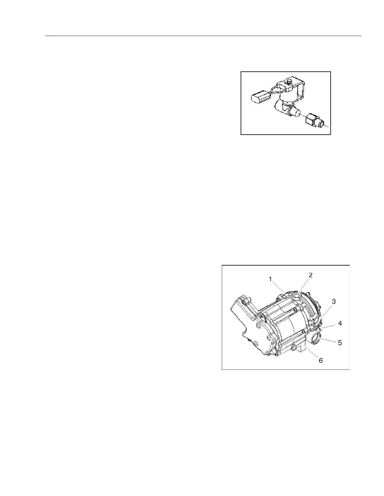
Figure 3-79. Electric Fuel Lock Off
1. Pressure Regulator Sec-
tion
2. Fuel Inlet
3. Coolant Passage
4. Primary Test Port
5. Secondary Test
Port
6. Voice Coil Section
Figure 3-80. EPR Assembly