SECTION 5 - JLG CONTROL SYSTEM
3121642 – JLG Lift – 5-7
Joystick Calibration
Using the Analyzer, in Access Level 1, go to MENU: CALIBRA-
TION: JOYSTICK and press ENTER.
1. Following the analyzer screen prompts:
a. Move the Joystick FORWARD and press ENTER.
b. Allow Joystick to be in CENTER position and press
ENTER.
c. Move the Joytstick REVERSE and press ENTER.
2. CAL COMPLETE or CAL FAILED will display on the ana-
lyzer.
3. Possible reasons if calibration failure:
a. The forward position must be a lower voltage than
reverse position.
b. The difference between center and forward & center
and reverse must be atleast 1V.
Tilt Sensor Calibration
1. Drive the machine onto a measured level surface (±0.5°
for both x and y axis).
2. Using the Analyzer, go to MENU: CALIBRATION; TILT SEN-
SOR. Press Enter. LEVEL VEHICLE will display. Press Enter
again to calibrate.
3. Both axis’ raw angles need to be within ±5.0°, otherwise
the machine is too unlevel and the software will prohibit
calibration. Should this occur, attempt to dissect the
three areas of error to find the primary contributor:
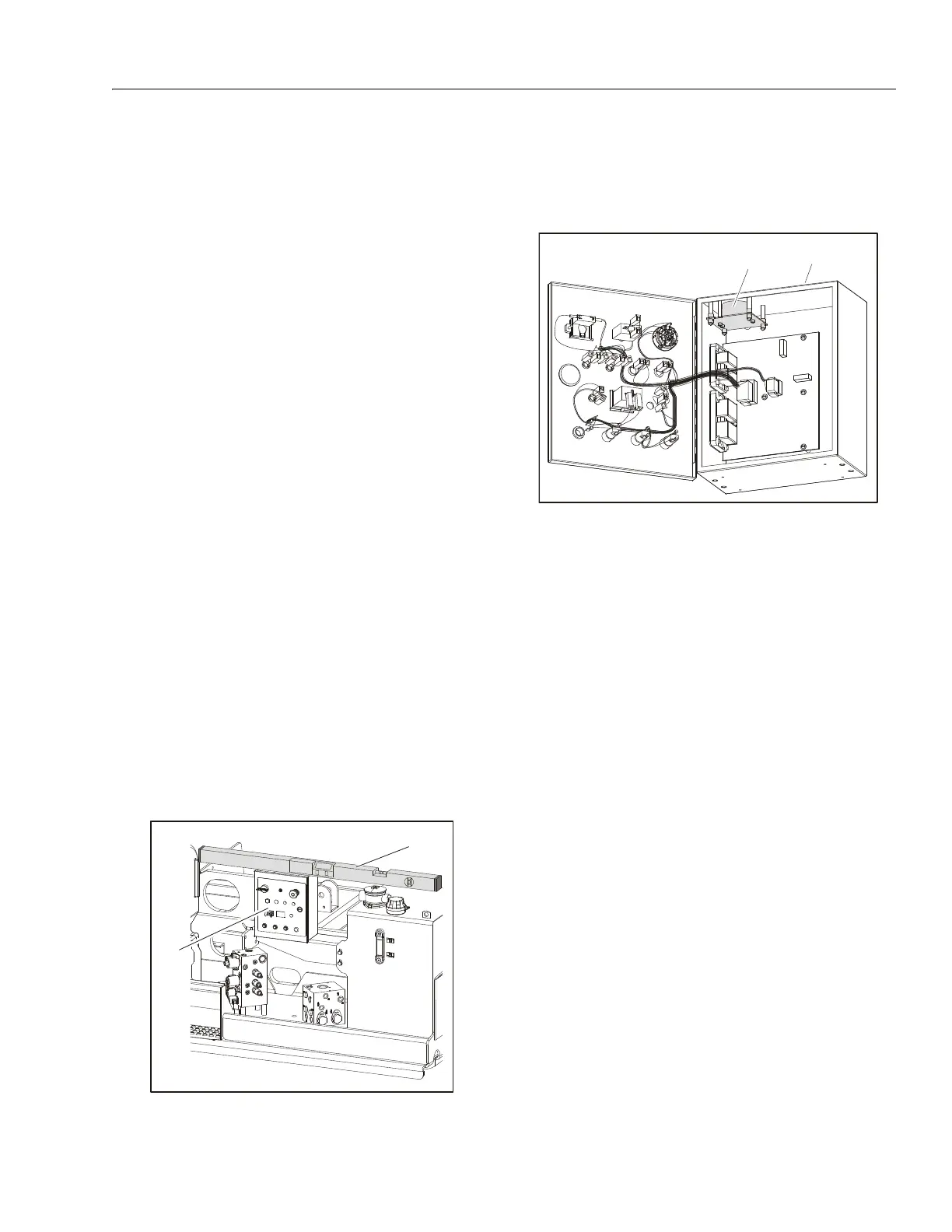
a. Machine mounting and/or grade:
With a digital level, measure the top of the Ground
Control box for levelness. If unable to get a good
reading, check the box’s mounting surface for level-
ness.
b. Tilt sensor mounting on machine or wedged
crooked in control box:
If the machine mounting/grade appears acceptable,
open the Ground Control box carefully. Observe
whether the tilt sensor is properly seated.
c. Tilt sensor has developed an offset shift:
Remove the tilt sensor from the Ground Control
box, but keep both the tilt sensor and Ground Con-
trol box electrically connected. Level one axis of the
tilt sensor and observe the raw reading (should be
within ±2.0°). Do the same for the other axis. If either
axis is greater than ±2.0°, replace the tilt sensor.
Some possible reasons that the tilt sensor will not calibrate
are:
a. The surface the machine is sitting on is off level by a
few degrees (flat doesn’t imply level; parking lots are
often not level).
b. The tilt sensor has failed one or both of the channels
(X axis and Y axis).
c. Tilt sensor has moisture intrusion that has shifted its
output.
d. Water and/or corrosion in the box has corrupted
electrical connections or caused a tilt sensor or
ground control board failure (observe any cracks in
the box).
e. The Ground Control Box, as mounted on the
machine, does not allow the tilt sensor to be level.
For the following troubleshooting steps, a bubble level
(smaller is better) will be needed and the machine must be on
a level surface:
1. On the Analyzer, go to Diagnostics/System and read the
tilt angle. If either angle reports +20.0°, there is an elec-
trical/electronic failure (tilt sensor, control board, electri-
cal connections).
a. Open the Ground Control Box.
1. Ground Control Box 2. Digital Level
1. Ground Control Box 2. Tilt Sensor