SECTION 3 - CHASSIS, PLATFORM & SCISSOR ARMS
3121642 – JLG Lift – 3-83
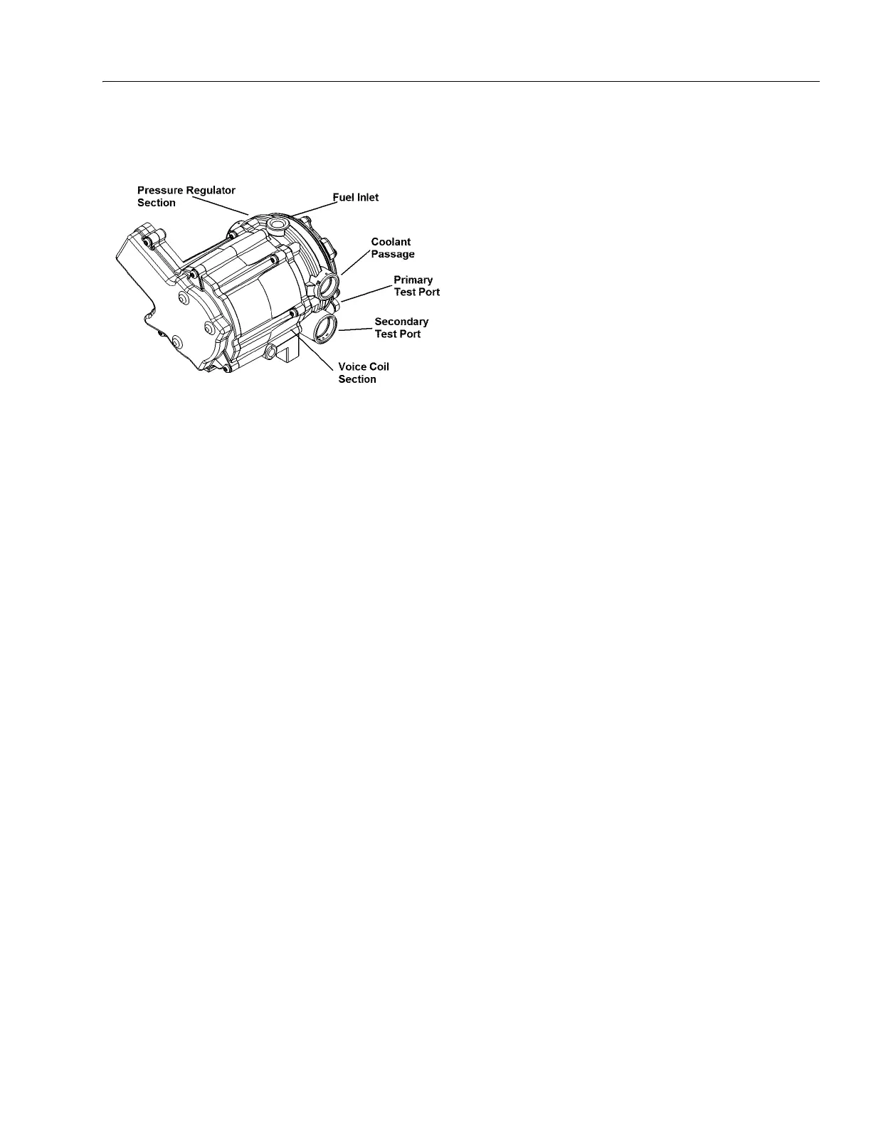
3.19 GM ENGINE LPG FUEL SYSTEM DIAGNOSIS
Fuel System Description
To maintain fuel and emission control on the LPG fuel system,
the Engine Control Unit (ECM) relies on numerous engine sen-
sor and output data from the Electronic Pressure Regulator
(EPR). The ECM will then determine the target fuel calibration
and command the EPR to reposition the voice coil to the
proper position which, subsequently repositions the second-
ary lever in the pressure regulator to maintain proper control.
The EPR and ECM will continue to communicate back and
forth during normal operation.
In the event that the EPR fails to communicate or the Commu-
nications Area Network (CAN) cable fails to transmit data, the
regulator will operate in an open loop configuration. As the air
valve vacuum in the mixer venturi is communicated to the sec-
ondary chamber of the regulator, the secondary diaphragm
will be drawn in a downwards motion. This downward motion
will cause the secondary lever to open, thus allowing more
fuel to enter the mixer.
In the (LPR), the fuel is vaporized and the pressure reduced in
two stages. The first stage reduces the pressure to approxi-
mately 1.0 to 3.0 psi (6.8 to 20.6 kPa). The second stage
reduces the pressure to approximately negative 1.5" of water
column.
The fuel is then drawn from the secondary chamber of the LPR
by the vacuum generated by air flowing through the mixer.
This vacuum signal is also used to generate lift for the mixer air
valve. This vacuum signal is most commonly referred to as air
valve vacuum. In the mixer, the fuel mixes with the air entering
the engine. This air/fuel mixture is then drawn into the engine
for combustion.
Diagnostic Aids
This procedure is intended to diagnose a vehicle operating on
LPG. If the vehicle will not continue to run on LPG, refer to
Hard Start for preliminary checks. Before proceeding with this
procedure, verify that the vehicle has a sufficient quantity of
fuel and that liquid fuel is being delivered to the LPR. Also,
ensure that the manual shut off valve on the LPG tank is fully
opened and that the excess flow valve has not been activated.
Tools Required:
• 7/16 Open end wrench (for test port plugs)
• DVOM (GM J 39200, Fluke 88 or equivalent)
• 12 volt test light
Diagnostic Scan Tool:
• Diagnostic Display tool
Pressure Gauges:
•IMPCO ITK-2 Test kit
• Water Column Gauge / Manometer (GM 7333-6 or equiva-
lent)
• 0-10 PSI Gauge
Test Description:
The numbers below refer to step numbers in Table 3-13, LPF
Fuel System Diagnosis.
5. This step determines if the LPR requires replacement.
6. This step determines if the problems are in the mechanical
side of the Pressure Regulator or the Electronic Voice Coil.
10. This step determines if the Mixer requires replacement.
14. This step determines if the Lock Off requires replacement.
17. This step determines if the Fuel Filter requires replacement.
Figure 3-93. EPR Assembly