SECTION 3 - CHASSIS, PLATFORM & SCISSOR ARMS
3-24 – JLG Lift – 3121642
Disassembly
NOTE: Removal of the endcap voids warranty.
During assembly, coat all moving parts with a film of clean
hydraulic oil. This assures that these parts will be lubricated
during start-up.
Replace all O-Rings and gaskets.
It is recommended that all O-rings be replaced. Lightly
lubricate all O-rings with clean petroleum jelly prior to
assembly.
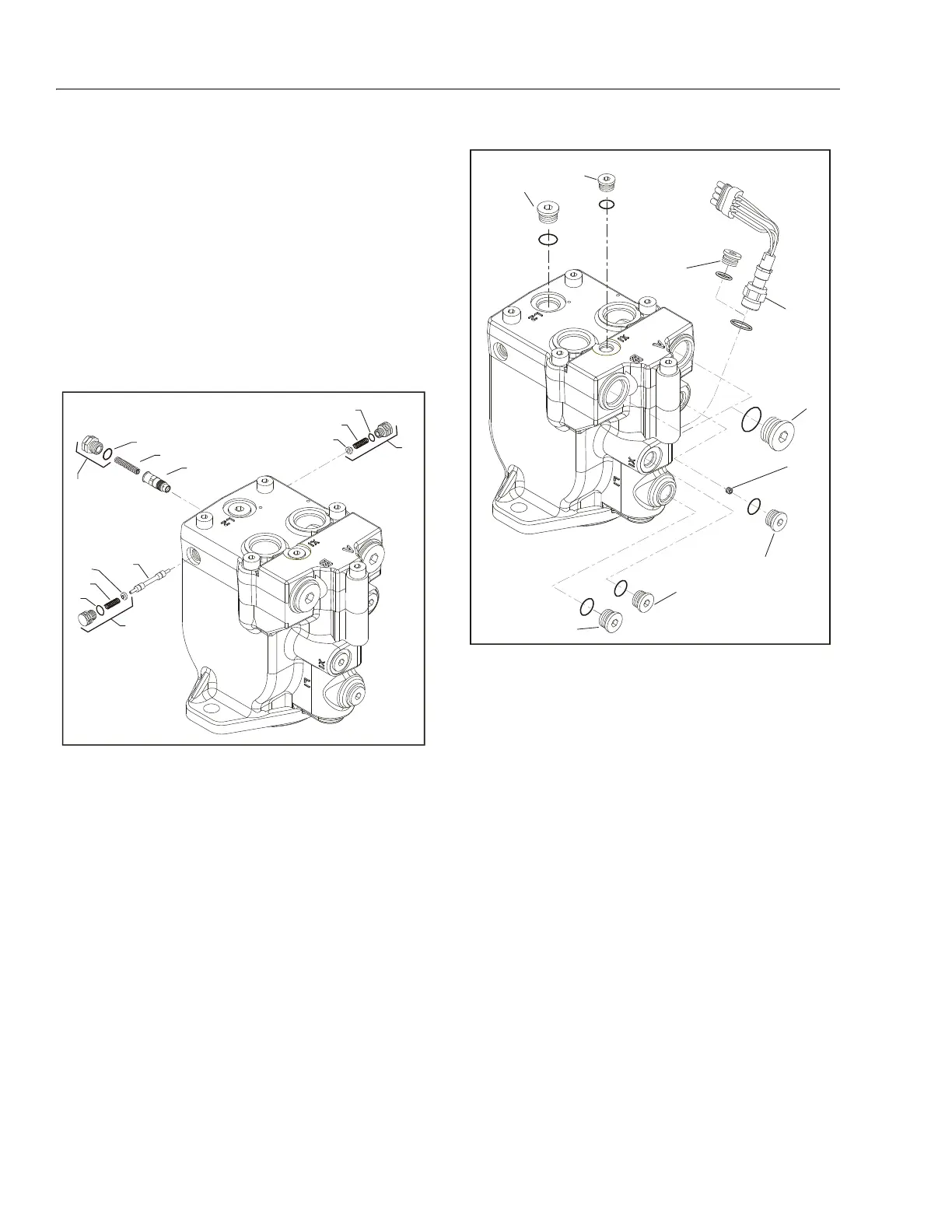
1. Using a 11/16 in wrench, remove plug (1) and (2).
2. Using a 5/8 in hex wrench, remove plug (3).
3. Remove O-rings (4, 5, and 6).
4. Using pliers, remove centering springs (7, 8, and 9).
5. Remove spring retaining washers (10 and 11).
6. Remove shift spool (12).
7. Remove orifice poppet (13).
8. Remove all fittings from the unit. Discard any O-rings on
the fittings.
9. Using an 11/16 in hex wrench, loosen the speed sensor
lock nut (14) if equipped. Then remove the speed sensor
using a 1/2 inch hex wrench. Units without speed sensor
have an O-ring plug (15) installed in that location;
remove it with a 1/4 inch internal hex wrench.
10. Using a 1/4 in internal hex wrench, remove control line
plugs (16, 17). Discard O-rings. Using a 3 mm hex
wrench, remove cavity plug (18, if equipped with two-
line control) from X2 cavity.
11. Using a 5/16 in internal hex wrench, remove drain plugs
(19, 20). Discard O-rings.
12. Using a 9/16 in internal hex wrench, remove work port
plugs (21, if equipped with axial ports). Discard O-rings.
1. Plug
2. Plug
3. Plug
4. O-ring
5. O-ring
6. O-ring
7. Spring
8. Spring
9. Spring
10. Washer
11. Washer
12. Shift Spool
13. Orifice Poppet
Figure 3-8. Loop Flushing Spool
14. Lock Nut
15. O-ring Plug
16. Control Line Plug
17. Control Line Plug
18. Cavity Plug
19. Drain Plug
20. Drain Plug
21. Work Port Plug
Figure 3-9. Plugs, Fittings, and Speed Sensor