SECTION 6 - GENERAL ELECTRICAL INFORMATION & SCHEMATICS
3121642 – JLG Lift – 6-9
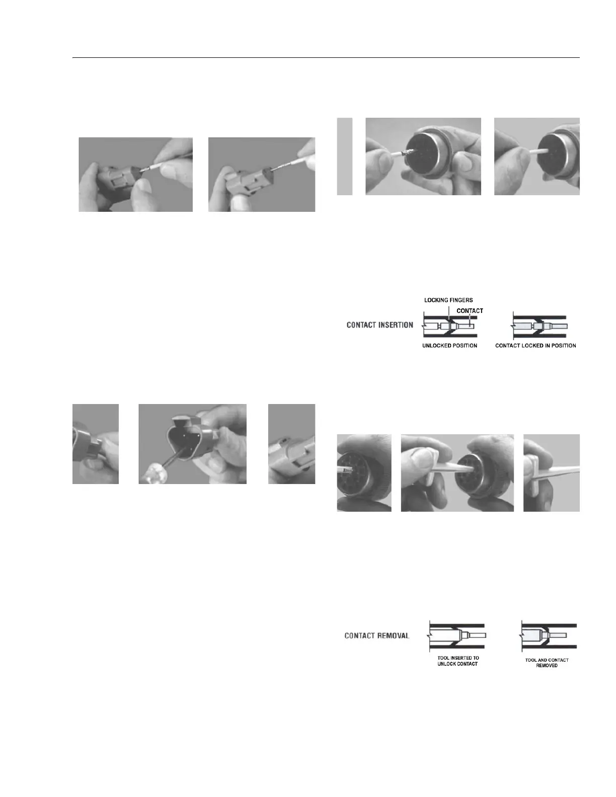
6.4 WORKING WITH DEUTSCH CONNECTORS
DT/DTP Series Assembly
Figure 6-12. DT/DTP Contact Installation
1. Grasp crimped contact about 25mm behind the contact
barrel.
2. Hold connector with rear grommet facing you.
3. Push contact straight into connector grommet until a
click is felt. A slight tug will confirm that it is properly
locked in place.
4. Once all contacts are in place, insert wedgelock with
arrow pointing toward exterior locking mechanism. The
wedgelock will snap into place. Rectangular wedges are
not oriented. Thy may go in either way.
NOTE: The receptacle is shown - use the same procedure for plug.
DT/DTP Series Disassembly
Figure 6-13. DT/DTP Contact Removal
5. Remove wedgelock using needlenose pliers or a hook
shaped wire to pull wedge straight out.
6. To remove the contacts, gently pull wire backwards,
while at the same time releasing the locking finger by
moving it away from the contact with a screwdriver.
7. Hold the rear seal in place, as removing the contact may
displace the seal.
HD30/HDP20 Series Assembly
Figure 6-14. HD/HDP Contact Installation
8. Grasp contact about 25mm behind the contact crimp
barrel.
9. Hold connector with rear grommet facing you.
10. Push contact straight into connector grommet until a
positive stop is felt. A slight tug will confirm that it is
properly locked in place.
Figure 6-15. HD/HDP Locking Contacts Into Position
NOTE: For unused wire cavities, insert sealing plugs for full envi-
ronmental sealing
HD30/HDP20 Series Disassembly
Figure 6-16. HD/HDP Contact Removal
11. With rear insert toward you, snap appropriate size
extractor tool over the wire of contact to be removed.
12. Slide tool along into the insert cavity until it engages
contact and resistance is felt.
13. Pull contact-wire assembly out of connector.
Figure 6-17. HD/HDP Unlocking Contacts
NOTE: Do not twist or insert tool at an angle.