SECTION 3 - CHASSIS, PLATFORM & SCISSOR ARMS
3-38 – JLG Lift – 3121642
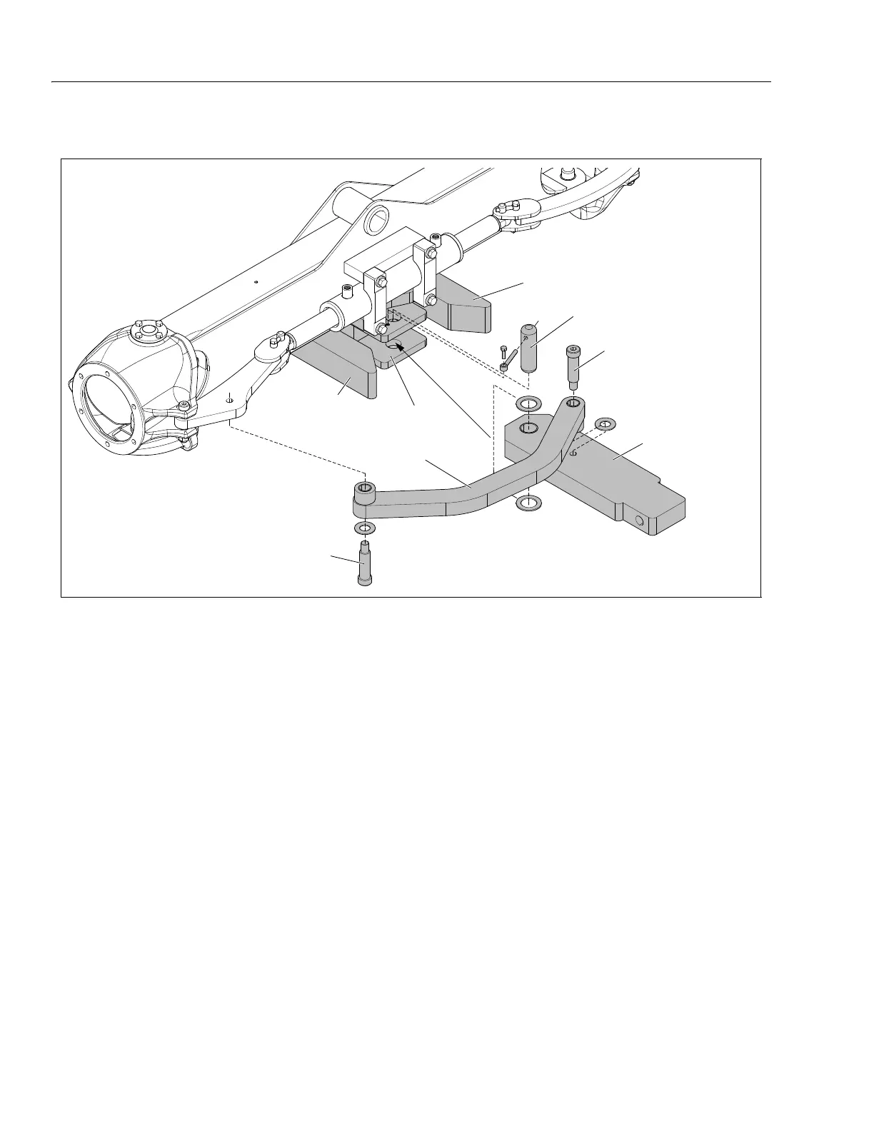
Front Axle - Tow Bar Installation (If Equipped)
INSTALLATION:
NOTE: Before assembly coat all bearing, pin, thrust washers, and
shoulder screw wear surfaces with a light coating of multi-
purpose grease. Keep screw threads free of grease since
thread locking compound will be used there.
1. Place the tow bar (3) into the axle mount (1) with a
thrust washer on the top and bottom, aligned with the
pivot pin hole.
2. Slide the tow bar pivot pin (5) down through the hole in
the top axle mount weldment and through the tow bar
and thrust washers, then into the lower axle mount
weldment.
3. Fix the tow bar pivot pin into place by sliding the banjo
locking pin through the hole in the pivot pin. Secure the
banjo locking pin to the upper tow bar mount with the
screw provided. Apply thread locking compound-(#242)
to threads of screw, then tighten.
4. Install the steering link (4) to the tow bar (3) with the
shoulder screw (6), placing a thrust washer between the
steering link and the tow bar as shown above. Apply
thread locking compound-(#242) to the shoulder screw
(6) threads, then tighten.
5. Attach the other end of the steering link (4) to the axle
tie rod assembly. Place a thrust washer under the head
of the shoulder screw (6), apply thread locking com-
pound-(#242) to the screw threads. Slide the screw and
thrust washer into the steering link and align with the
mounting hole in the tie rod assembly, tighten the
screw.
If removal is required, tow bar can be completely removed by
removing the pivot pin (5) and the tie rod - tow bar shoulder
screw (6). Place all loose parts in a clean plastic bag for later
use.
When re-installing repeat all steps except step (4) since this
connection should not have required disassembly.
2. Tow Bar Axle Mount
3. Tow Bar Steering Stops
4. Tow Bar
5. Steering Link
6. Pivot Pin
7. Tie Rod/Tow Bar Shoulder Screws
Figure 3-30. Tow Bar Installation (If Equipped)