SECTION 3 - CHASSIS, PLATFORM & SCISSOR ARMS
3121642 – JLG Lift – 3-79
6. Remove the lock pin from the vapor fitting on the regu-
lator housing. Remove the fitting and hose and retain
the pin.
7. Remove the lock pin from the pressure sensor on the
regulator housing. Remove the sensor and retain the
pin.
8. Using clamp pliers, pinch off the hoses on the coolant
lines to the regulator.
9. Remove the lock pin from both water fittings on the reg-
ulator housing. Remove the fittings and hoses and retain
the pin.
10. Disconnect the EPR electrical connector.
11. Remove the three nuts from the EPR isolators and the
EPR mounting bracket.
12. Remove the EPR from the bracket.
13. Remove the three mounting isolators.
INSTALLATION:
DO NOT USE TEFLON TAPE ON ANY FUEL FITTING. USE A LIQUID PIPE THREAD
SEALANT WHEN INSTALLING FITTINGS.
CHECK ALL THE O-RINGS ON THE VAPOR AND WATER FITTINGS FOR ANY DAM-
AGE. REPLACE IF NECESSARY.
LUBE ALL THE O-RINGS WITH AN O-RING LUBE BEFORE INSTALLING.
1. Install the three rubber isolators to the bottom of the
EPR.
2. Install the EPR assembly to the bracket and tighten the
retaining nuts.
NOTE: Do not overtighten the isolators and cause a separation of
the isolators.
3. Install the fuel temperature sensor into the regulator
opening and lock in place with the locking pin. Connect
the electrical connector.
4. Insert the fuel vapor line and fitting into the regulator
port and lock in place with the locking pin.
5. Install both the water hoses and fittings into the regula-
tor and lock in place with the locking pin. Remove the
clamp pliers from the hoses.
6. Install the electric lock off into the regulator inlet and
tighten into proper location. Connect the electrical con-
nector.
7. Connect the fuel supply line and tighten until fully
seated.
8. Connect the EPR electrical connector.
9. Open the manual valve.
10. Start the vehicle and leak check the propane fuel system
at each serviced fitting. Refer to Propane Fuel System
Leak Test.
PRESSURE REGULATOR SECTION REMOVAL:
1. Remove the EPR. Refer to EPR Removal Procedure.
2. Remove the six regulator to voice coil screws using the
special tool and separate the regulator from the actua-
tor.
DO NOT REMOVE THE SECONDARY DIAPHRAGM RETAINING PLATE AND DIA-
PHRAGM. THIS WILL VOID THE WARRANTY OF THE ACTUATOR SECTION.
PRESSURE REGULATOR SECTION INSTALLATION:
1. Install the regulator to the actuator section using the six
retaining screws and tighten to 70 in.lbs. (8 Nm).
2. Install the EPR. Refer to EPR Installation.
Temperature Manifold Absolute Pressure (TMAP)
Sensor
REMOVAL:
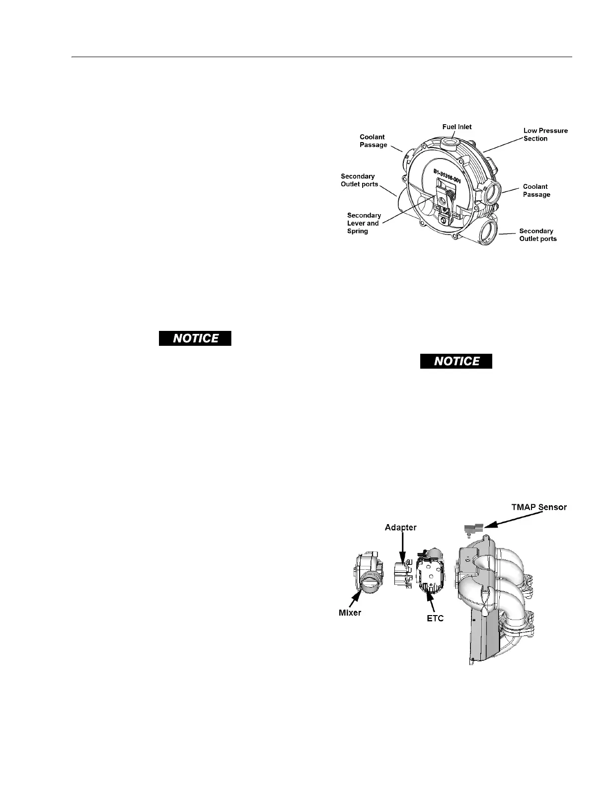
Figure 3-90. Pressure Regulator Section
Figure 3-91. (TMAP) Sensor & Electronic Throttle
Control (ETC)