SECTION 3 - CHASSIS, PLATFORM & SCISSOR ARMS
3121642 – JLG Lift – 3-69
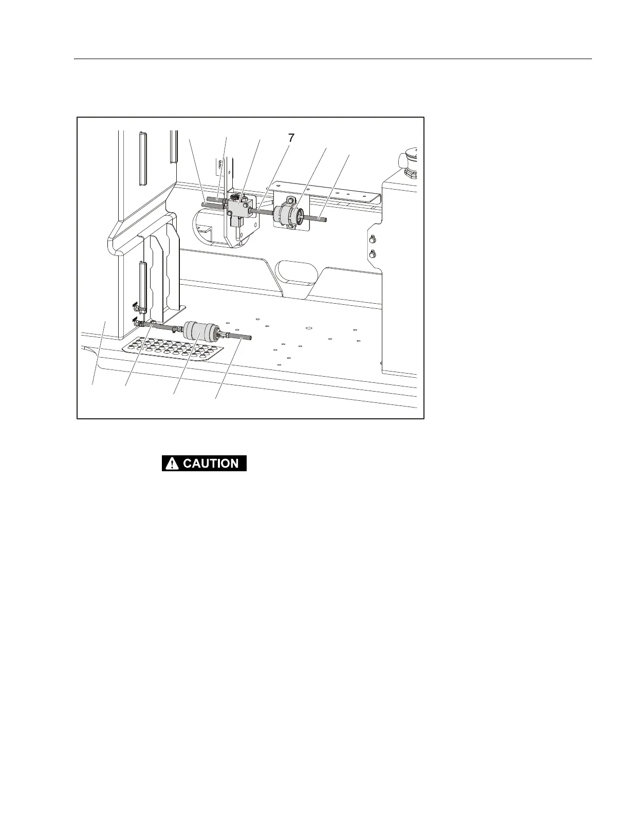
Fuel Components
ALLOW ENGINE AND COMPONENTS TO COOL DOWN BEFORE SERVICING.
REMOVAL:
1. Disable machine operation.
2. Disconnect, label and cap all fuel lines (3, 4, 6, 7, 9, 10).
NOTE: Fuel will still be in the fuel lines. Drain the lines and store
fuel in a suitable container.
3. Remove the bolts, nuts and washers attaching the fuel
pump (1), fuel filter (5) and fuel regulator (8) to the
machine.
INSTALLATION:
1. Follow Removal Steps in reverse.
2. Uncap and connect the fuel line (3) to the supply valve
of the fuel tank (2) and the fuel pump (1).
3. Uncap and connect the fuel line (4) to the fuel pump
and fuel filter (5).
4. Uncap and connect the fuel line (7) to the fuel filter and
fuel regulator (8).
5. Uncap and connect the fuel line (9) to the fuel regulator
and the return valve on the fuel tank.
6. Uncap and connect the fuel line (10) to the fuel regula-
tor and the fuel rail on the engine.
1. Fuel Pump
2. Fuel Tank
3. Fuel Line - Supply from Tank
4. Fuel Line - to Fuel Filter
5. Fuel Filter
6. Fuel Line - to Fuel Pump
7. Fuel Line
8. Fuel Regulator
9. Fuel Line - Return to Tank
10. Fuel Line - to Engine
Figure 3-75. Fuel Components (GM Engine)