SECTION 3 - CHASSIS, PLATFORM & SCISSOR ARMS
3-12 – JLG Lift – 3121642
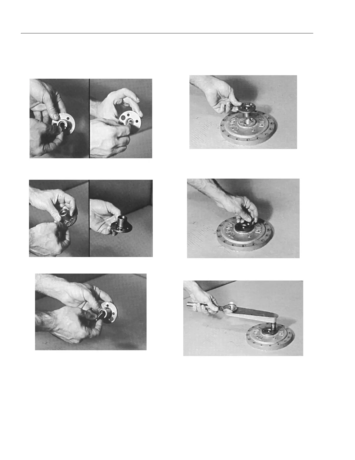
Cover Sub-Assembly
1. Using the disconnect rod, push o-ring (6F) into the
groove inside the cover cap (6B).
2. Place the o-ring (6G) onto the cover cap (6B) so that it
rests against the flange of the cover cap.
3. Insert disconnect rod (6E) into cover cap (6B).
4. Set cover (6A) on table, exterior side up. Place cover cap
(6B) onto cover (6A), aligning the pipe plug hole in the
cover cap over the pipe plug hole in the cover.
5. Place two of the cover cap bolts (6C) into any two bolt
holes that are 180° apart on the cover cap (6B) and
tighten bolts.
6. Using a torque wrench, apply 2.95 to 3.69 ft. lbs. (4 to 5
Nm) of torque to both bolts (6C).