SECTION 3 - CHASSIS, PLATFORM & SCISSOR ARMS
3121642 – JLG Lift – 3-17
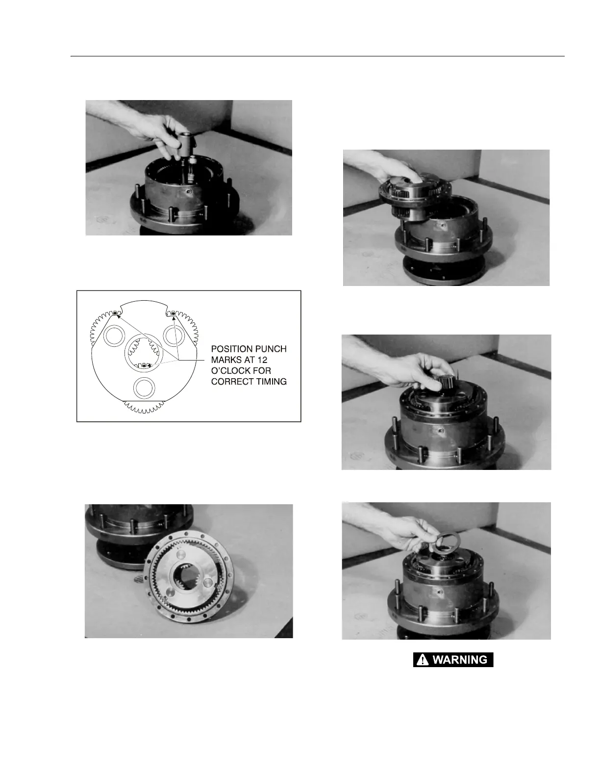
10. Place thrust spacer (9) onto input shaft (7).
11. Set carrier sub-assembly (3) on a flat work surface so the
large ends of cluster gears (3F) face up. Locate the
punch marks on the face of each cluster gear (3F) and
position them at 12 o’clock.
12. With "X" marked side facing up, place the ring gear (4)
around cluster gears (3F).
NOTE: This will hold the punch marks in position while installing
the carrier into the hub.
13. Place the carrier sub assembly (3) and ring gear (4)
together into mesh with internal gear (2), aligning the
"X" marked shoulder bolt hole in the ring gear (4) over
one of the shoulder bolt holes in the hub. Mark the loca-
tion of shoulder bolt holes on the outside of ring gear
and hub.
NOTE: You may lift the ring gear off the hub to align the shoulder
bolt holes. The ring gear and carrier are installed together
only to keep the punch marks on the carrier in place.
14. With the internal splines facing up (counterbore end fac-
ing down), place input gear (8) into mesh with carrier
sub-assembly (3).
15. Oil all exposed surfaces inside the hub (1G). Place thrust
washer (11) into the counterbore in top of the carrier.
BEWARE OF SHARP EDGES IN THE COUNTERBORE WHEN YOU INSTALL THE O-
RING.
Figure 3-4. Cluster Gear Punch Marks