SECTION 3 - CHASSIS, PLATFORM & SCISSOR ARMS
3-16 – JLG Lift – 3121642
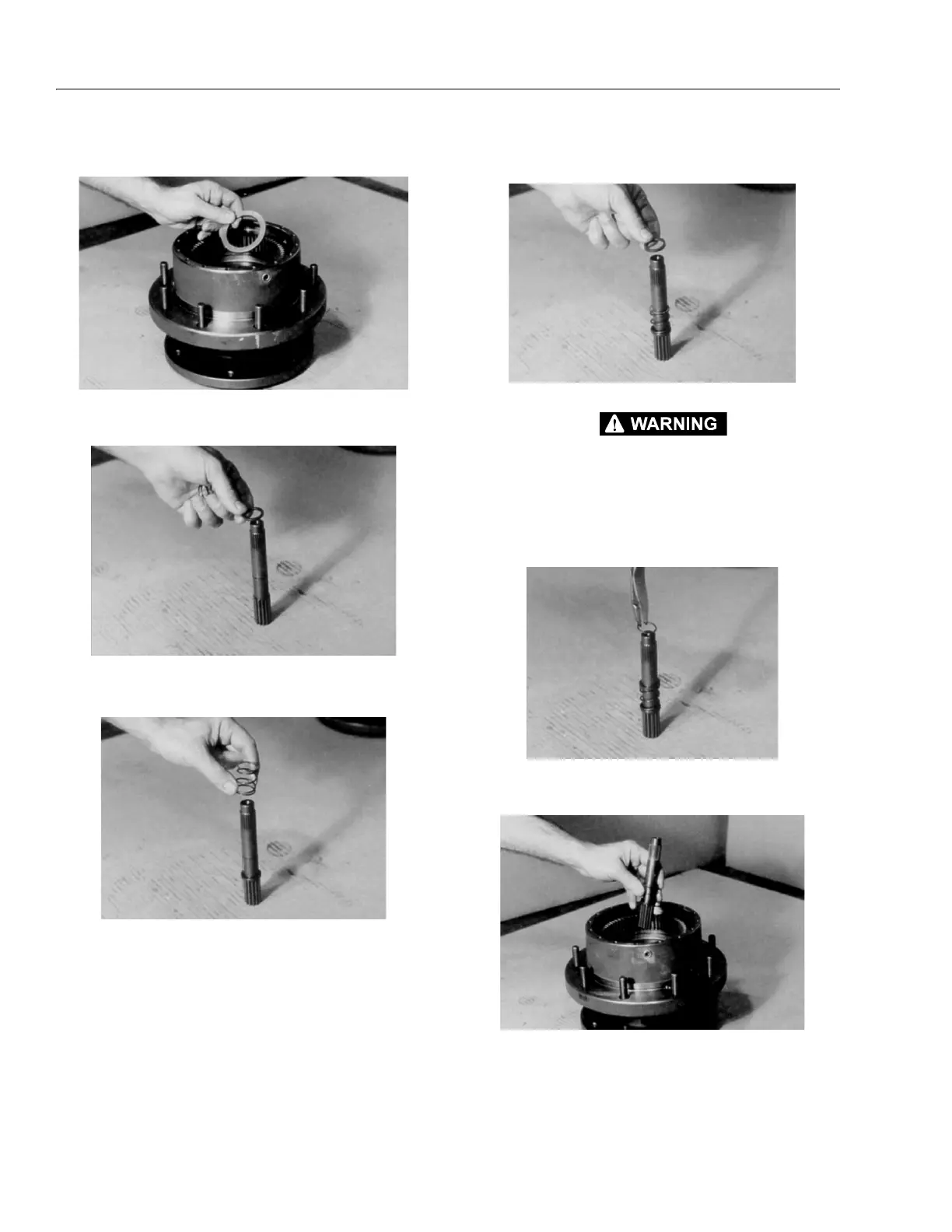
4. Place thrust washer (11) around spindle (1A) so it rests
on the bottom of the internal gear (2).
5. Stand input shaft (7A) on its splined end. Place one
spacer (7D) onto the smooth end of input shaft (7A).
6. Place one spring (7C) onto the smooth end of input
shaft (7A).
7. Place other spacer (7D) onto the smooth end of input
shaft (7A).
WEAR SAFETY GLASSES DURING THIS STEP, AND BE AWARE THAT SPRING AND
SPACERS, COMPRESSED BY RETAINING RING, MAY POP SUDDENLY OFF SHAFT
IF THE RING IS RELEASED BEFORE IT IS PROPERLY IN PLACE.
8. Using retaining ring pliers, insert retaining ring (7B) into
the groove on input shaft (7A) by compressing the
spring and spacers together.
9. With large splined end down, place input shaft sub-
assembly (7) into spindle (1A).