SECTION 6 - GENERAL ELECTRICAL INFORMATION & SCHEMATICS
6-6 – JLG Lift – 3121642
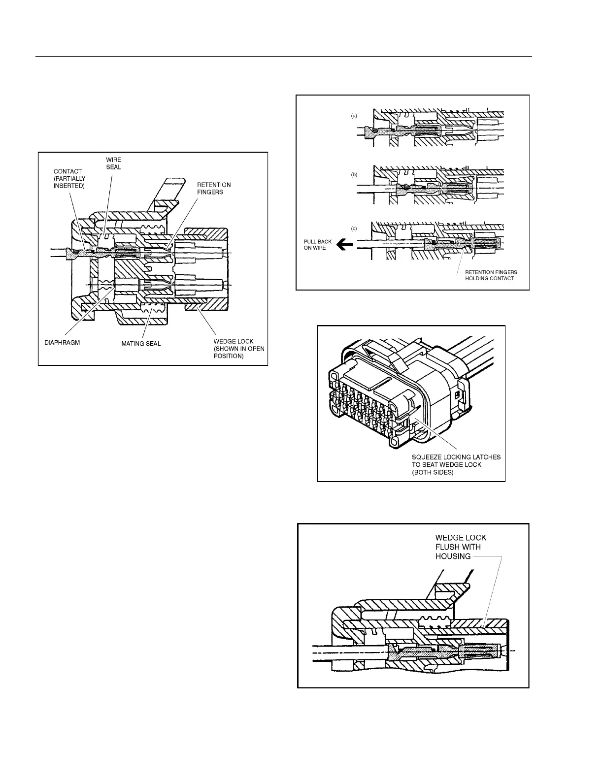
Assembly
Check to be sure the wedge lock is in the open, or as-shipped,
position (See Figure 6-6. Connector Assembly (1 of 4)). Proceed
as follows:
Figure 6-6. Connector Assembly (1 of 4)
1. To insert a contact, push it straight into the appropriate
circuit cavity as far as it will go (See Figure 6-7. Connec-
tor Assembly (2 of 4)).
2. Pull back on the contact wire with a force of 1 or 2 lbs. to
be sure the retention fingers are holding the contact
(See Figure 6-7. Connector Assembly (2 of 4)).
3. After all required contacts have been inserted, the
wedge lock must be closed to its locked position.
Release the locking latches by squeezing them inward
(See Figure 6-8. Connector Assembly (3 of 4)).
4. Slide the wedge lock into the housing until it is flush
with the housing (See Figure 6-9. Connector Assembly
(4 of 4)).
Figure 6-7. Connector Assembly (2 of 4)
Figure 6-8. Connector Assembly (3 of 4)
Figure 6-9. Connector Assembly (4 of 4)