SECTION 3 - CHASSIS, PLATFORM & SCISSOR ARMS
3121642 – JLG Lift – 3-49
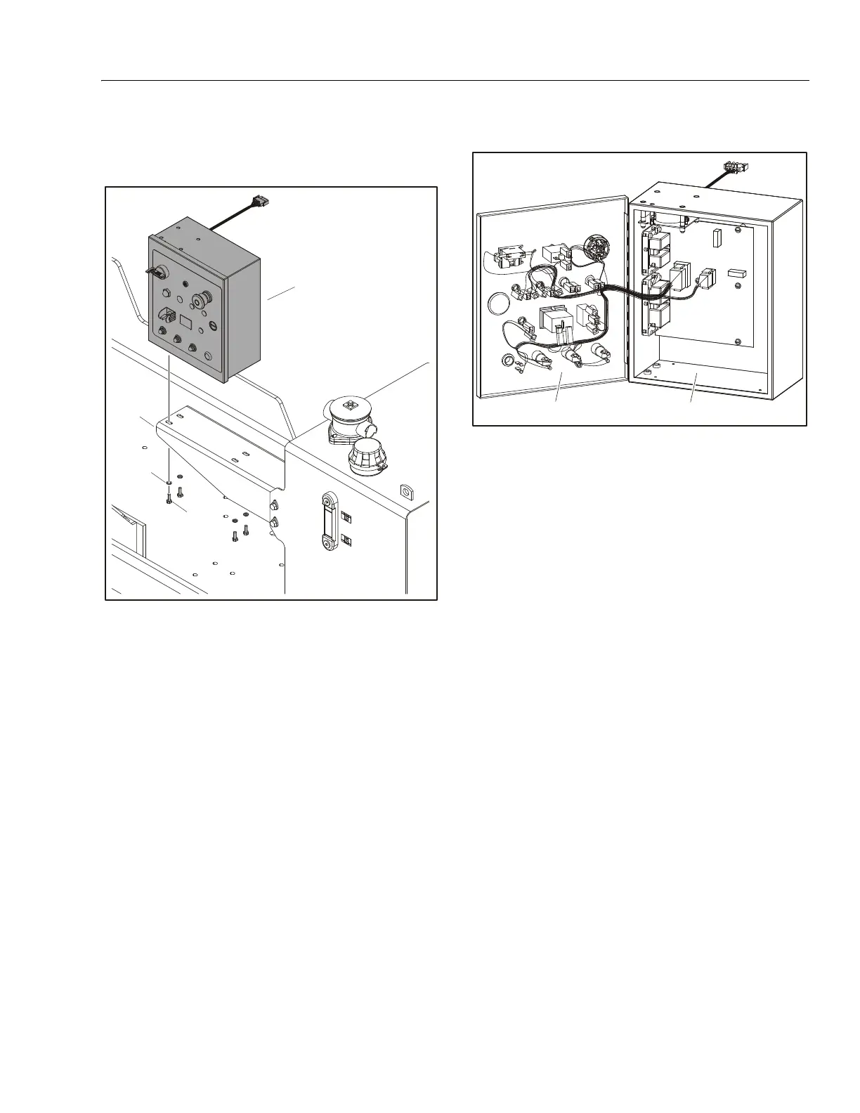
3.10 GROUND CONTROL STATION
Control Station Removal
REMOVAL:
1. Disconnect and label the harnesses from the ground
control box (1).
2. Remove the ground control box from the control box
mount (2) by removing the four bolts (3) and lockwash-
ers (4).
INSTALLATION:
1. Follow Removal Steps in reverse.
NOTE: Apply Loctite® #242 to the four bolts (3).
Ground Control Station
DISASSEMBLY:
1. Disconnect the harnesses from the ground control box
(1).
2. Open the lid (2) to gain access to components inside the
ground control box.
3. Disconnect any wires and/or plugs from damaged com-
ponents.
4. Remove and replace components if necessary.
ASSEMBLY:
1. Reattach any wires and/or plugs.
2. Close lid (2) and secure.
3. Reattach harnesses to the ground control box (1).
NOTE: If tilt sensor is removed and replaced, it must be calibrated
(refer to Section 5.2, Calibrations).
1. Ground Control Box
2. Control Box Mount
3. Bolt, 1/4"-20NC x 3/4"
4. Lockwasher
Figure 3-44. Ground Control Station Removal
1. Ground Control Box 2. Lid
Figure 3-45. Ground Control Station