SECTION 3 - CHASSIS, PLATFORM & SCISSOR ARMS
3-26 – JLG Lift – 3121642
18. Remove minimum angle stop (29) and servo spring (30)
from the housing.
19. Turn the housing on its side and remove the cylinder kit
assembly (31). Set the assembly aside, being careful not
to scratch the running surface.
NOTE: Grooves on the surface of the cylinder kit identify its dis-
placement:
20. Turn the housing over and remove the snap ring (32)
retaining the shaft seal and support washer. Remove the
support washer (33) and carefully pry out the shaft seal
(34). Discard the seal.
To avoid damaging the shaft during seal removal, install
a large sheet metal screw into the chuck of a slide ham-
mer. Drive the screw into the seal surface and use the
slide hammer to pull the seal.
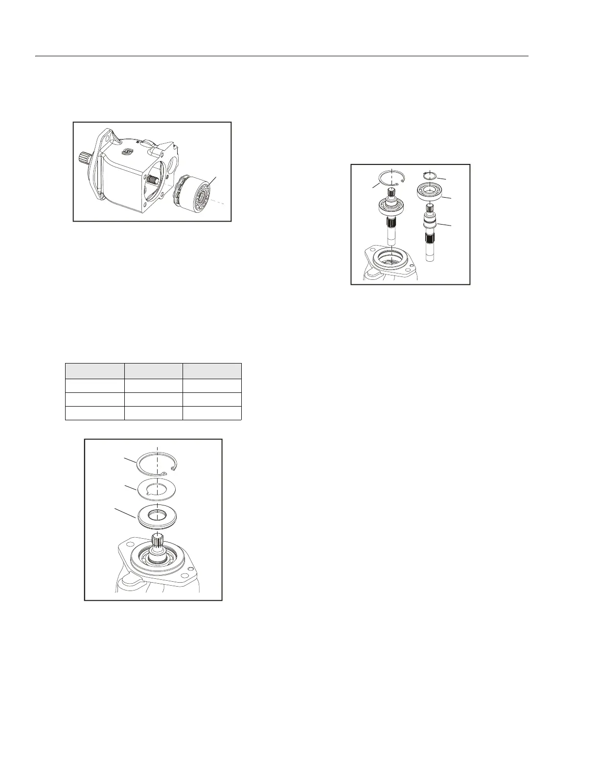
21. Remove the inner snap ring (35) and the shaft / bearing
assembly.
22. Remove the snap-ring (36) retaining the shaft front
bearing. Pull the bearing (37) off of the shaft (38).
Table 3-6. Displacement Identifiers
# of Grooves Frame L Frame K
12538
23045
335- -
31. Cylinder Kit Assembly
Figure 3-12. Cylinder Kit
32. Snap Ring
33. Support Washer
34. Shaft Seal
Figure 3-13. Shaft Seal
35. Inner Snap Ring
36. Snap Ring
37. Bearing
38. Shaft
Figure 3-14. Shaft & Front Bearing