SECTION 3 - CHASSIS, PLATFORM & SCISSOR ARMS
3-46 – JLG Lift – 3121642
3.8 SCISSOR ARMS
Lift Cylinder Removal
REMOVAL:
NEVER WORK UNDER ELEVATED SCISSOR ARMS WITHOUT FIRST PROPERLY
BRACING/BLOCKING SCISSOR ARM ASSEMBLY.
1. Remove platform (refer to Figure 3-37.).
2. Elevate the scissor arm assembly enough to gain access
to the upper and lower connection pins (2, 6). Block/
brace scissor arms and disable machine.
3. Disconnect, cap and label all hydraulic lines connected
to lift cylinder (1). Disconnect and label all electrical
wires connected to lift cylinder.
4. Attach lifting straps to overhead crane and lift cylinder
and support cylinder before attempting to remove from
arm assembly.
5. Remove the upper pin (2) by removing the bolt (3), nut
(4) and collar (5). Push pin out.
6. Remove the lower pin (6) by removing the bolt (7) and
nut (8). Push pin out.
7. Carefully lift cylinder up and out of arm assembly.
INSTALLATION:
1. Follow Removal Steps in reverse.
2. After assembly, operate lift cylinder to ensure proper
operation.
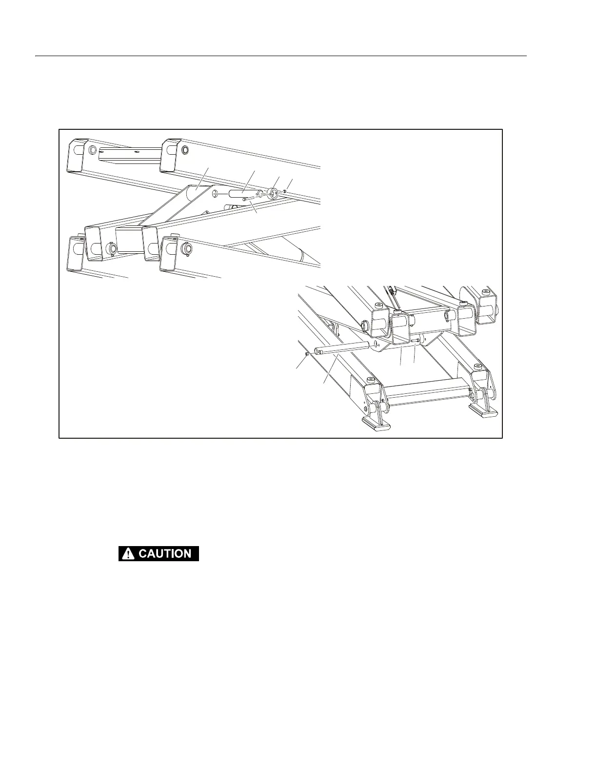
NOTE: Refer to Figure 4-29., Lift Cylinder for cylinder breakdown.
Top Connection Point
Bottom Connection
Po in t
1. Lift Cylinder
2. Pin
3. Bolt, 3/8"-16NC x 3"
4. Nut
5. Collar
6. Pin
7. Bolt, 1/2"-13NC x 1 5/8"
8. Nut
Figure 3-41. Lift Cylinder Removal