SECTION 3 - CHASSIS, PLATFORM & SCISSOR ARMS
3-70 – JLG Lift – 3121642
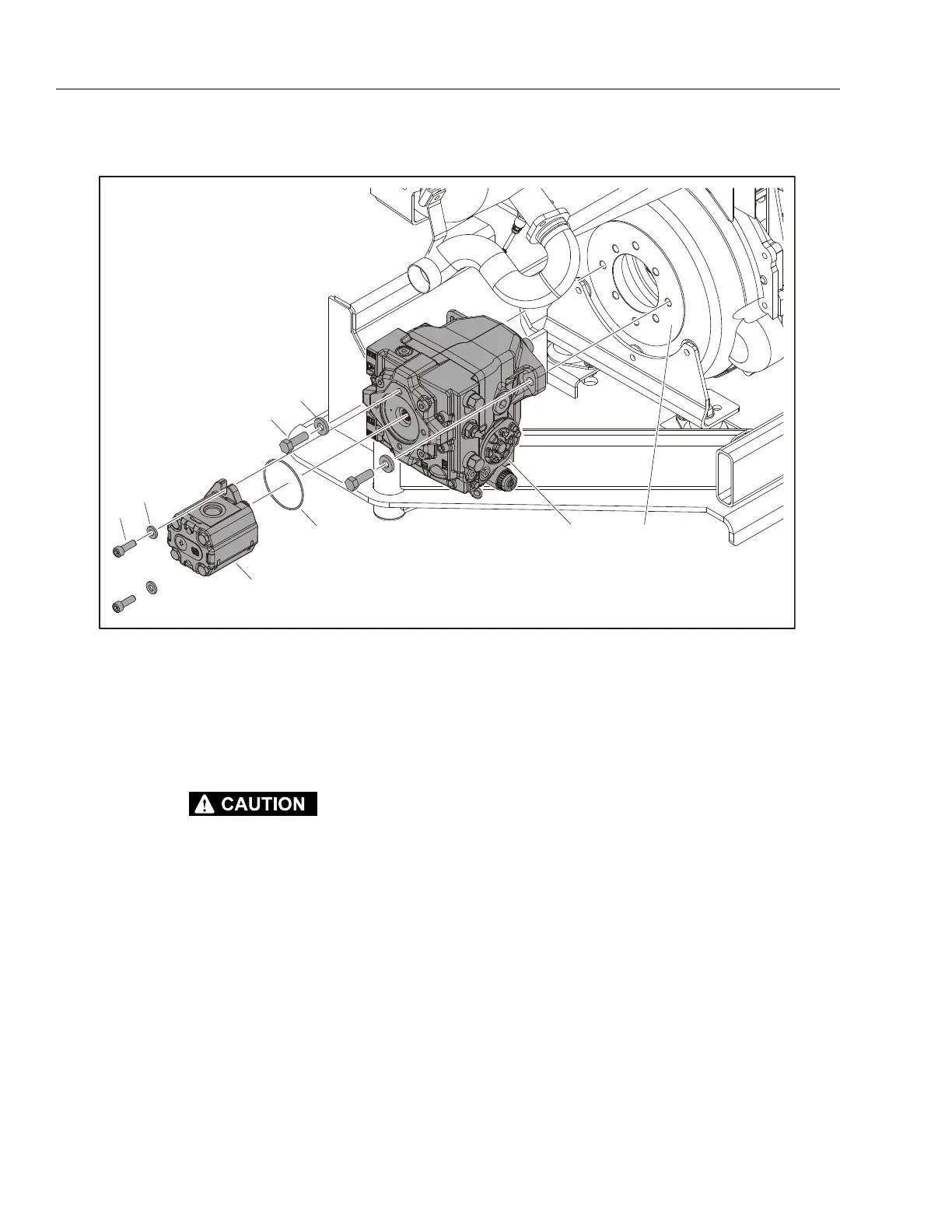
Pumps
ALLOW ENGINE AND COMPONENTS TO COOL DOWN BEFORE SERVICING.
REMOVAL:
1. Disable machine operation. Disconnect, cap and label all
hydraulic hoses connected to pumps (1, 4). Disconnect
and label all wiring connected to pumps.
2. Remove the two bolts (2) and washers (3) attaching the
gear pump (1) to the axial pump (4). Carefully remove
the gear pump.
3. Remove and discard the o-ring (4).
4. Remove the two bolts (5) and washers (6) attaching the
axial pump to the flange (7) of the coupling. Carefully
remove the axial pump.
INSTALLATION:
1. Follow Removal Steps in reverse.
NOTE: Apply Loctite® #242 to bolts (2, 5).
Apply grease to internal splines of pump coupling and
external splines of axial pump (4) shaft prior to installing
pump.
Install a new o-ring (4) during installation.
NOTE: Refer to Section 4.10, Gear Pump and Section 4.11, Axial HI
45 Pump for more information on pumps.
1. Gear Pump
2. Bolt, 3/8"-16NC x 1"
3. Washer
4. O-ring
5. Axial HI 45 Pump
6. Bolt, 1/2"-13NC x 1 1/2"
7. Washer
8. Coupling Flange
Figure 3-76. Pump Assemblies (GM Engine)