SECTION 3 - CHASSIS, PLATFORM & SCISSOR ARMS
3121642 – JLG Lift – 3-39
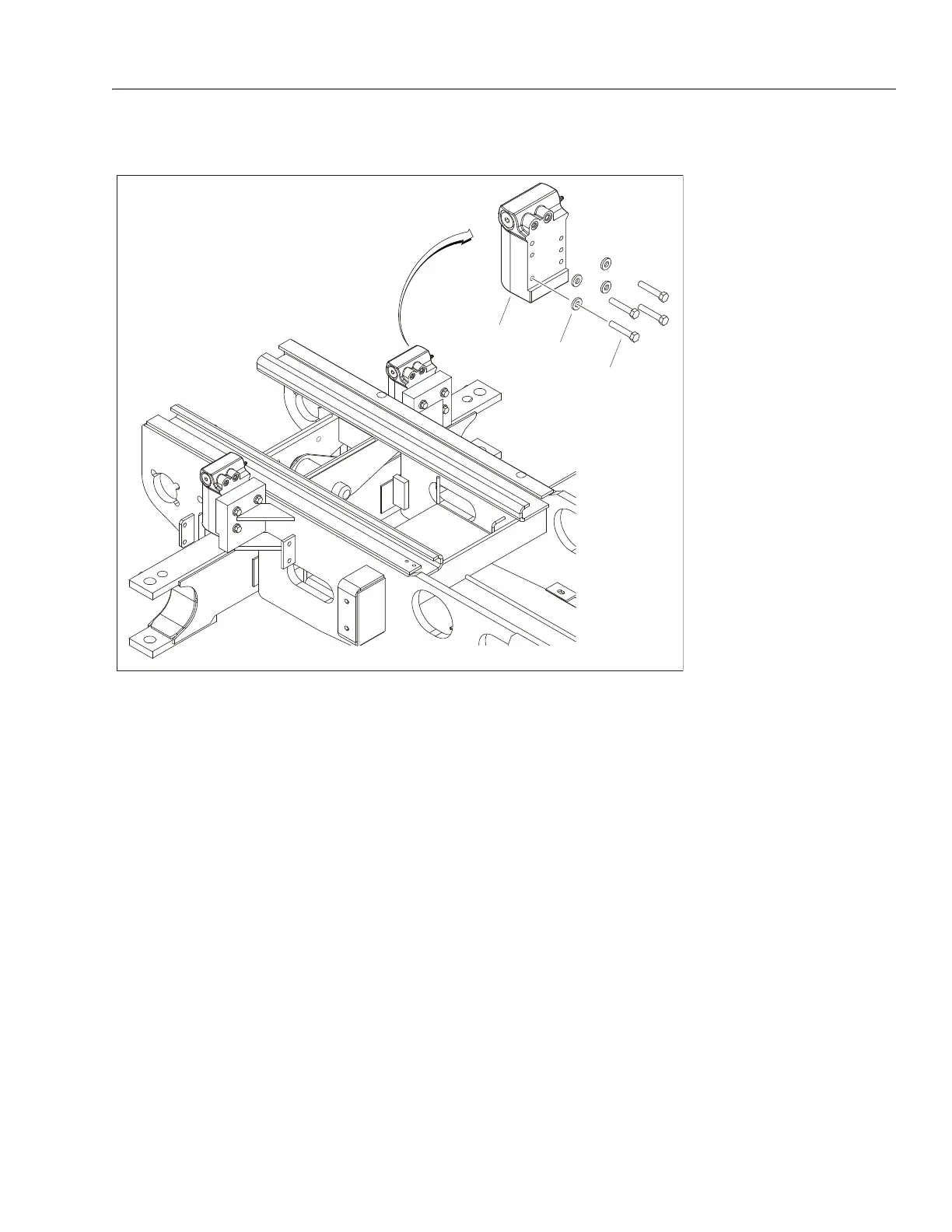
Axle Lockout Cylinder
REMOVAL:
1. Disable machine operation.
2. Disconnect, cap and label hydraulic lines on the axle
lockout cylinder (1).
3. Remove the four bolts (2) and washers (3) connecting
the cylinder to the frame.
4. Carefully remove cylinder from the frame.
INSTALLATION:
1. Attach cylinder to frame using four bolts (2) and washers
(3).
NOTE: Apply Loctite® #242 and Loctite® Primer #7471 to bolts (2).
2. Uncap and reconnect hydraulic lines to cylinder.
NOTE: Refer to Section 4.14, Cylinder Assemblies for axle lockout
cylnder breakdown and bleeding procedure.
3. Operate axle lockout cylinder function to ensure proper
functioning.
1. Axle Lockout Cylinder
2. Bolt, 1/2"-11NC x 2 3/4"
3. Washer
Figure 3-31. Axle Lockout Cylinder