SECTION 1 - SPECIFICATIONS
1-12 – JLG Lift – 3121642
Propane Fuel Filter Replacement
REMOVAL:
1. Relieve the propane fuel system pressure. Refer to Propane
Fuel System Pressure Relief.
2. Disconnect the negative battery cable.
3. Slowly loosen the Filter housing retaining bolt and remove
it.
4. Pull the filter housing from the Electric lock off assembly.
5. Locate Filter magnet and remove it.
6. Remove the filter from the housing.
7. Remove and discard the housing seal.
8. Remove and discard the retaining bolt seal.
9. Remove and discard mounting plate to lock off O-ring seal.
INSTALLATION:
BE SURE TO REINSTALL THE FILTER MAGNET INTO THE HOUSING BEFORE
INSTALLING NEW SEAL.
1. Install the mounting plate to lock off O-ring seal.
2. Install the retaining bolt seal.
3. Install the housing seal.
4. Drop the magnet into the bottom of the filter housing.
5. Install the filter into the housing.
6. Install the retaining bolt into the filter housing.
7. Install the filter up to the bottom of the electric lock off.
8. Tighten the filter retaining bolt to 106 in.lbs. (12 Nm).
9. Open manual shut-off valve. Start the vehicle and leak
check the propane fuel system at each serviced fitting.
Refer to Propane Fuel System Leak Test.
Propane Fuel System Pressure Relief
THE PROPANE FUEL SYSTEM OPERATES AT PRESSURES UP TO 312 PSI (21.5
BAR). TO MINIMIZE THE RISK OF FIRE AND PERSONAL INJURY, RELIEVE THE
PROPANE FUEL SYSTEM PRESSURE (WHERE APPLICABLE) BEFORE SERVICING
THE PROPANE FUEL SYSTEM COMPONENTS.
To relieve propane fuel system pressure:
1. Close the manual shut-off valve on the propane fuel tank.
2. Start and run the vehicle until the engine stalls.
3. Turn the ignition switch OFF.
RESIDUAL VAPOR PRESSURE WILL BE PRESENT IN THE FUEL SYSTEM. ENSURE
THE WORK AREA IS WELL VENTILATED BEFORE DISCONNECTING ANY FUEL
LINE.
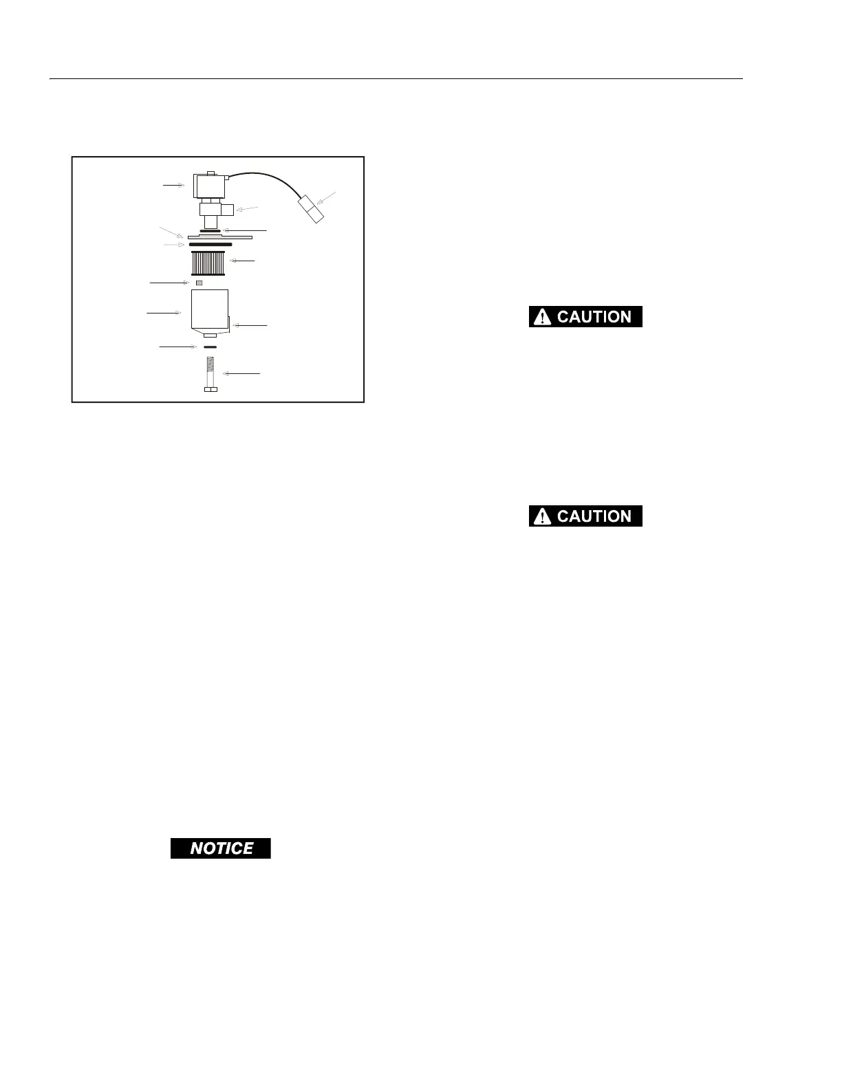
1. Electric Lock Off Solenoid
2. Mounting Plate
3. Housing Seal
4. Filter Magnet
5. Filter Housing
6. Seal
7. Electrical Connec-
tor
8. Fuel Outlet
9. O-ring
10. Filter
11. Fuel Inlet
12. Retaining Bolt
Figure 1-5. Filter Lock Assembly