SECTION 3 - CHASSIS, PLATFORM & SCISSOR ARMS
3121642 – JLG Lift – 3-3
Drive Assembly
REMOVAL:
SHUT MACHINE OFF, BRACE AXLES AND CHALK WHEELS TO PREVENT
MACHINE FROM MOVING DURING REPAIRS.
1. Disconnect, cap and label all hydraulic lines attached to
Drive Motor/Hub Assembly (3). If applicable, disconnect
all electrical wiring.
2. With axle raised and supported, remove the Tires (1)
from the drive motor/hub assembly by removing the 9
Lugnuts (2).
3. Remove the Drive Motor/Hub Assembly (3) by removing
the 6 Bolts (4) and Hardened Washers (5).
INSTALLATION:
1. Follow "Removal" procedures in reverse order.
2. Refer to Table 3-1, Wheel Torque Chart when torqueing
Lugnuts (2).
NOTE: For detailed information on the Drive Motor/Hub Assem-
bly, refer to Section 3.3, Drive Hub (Fairfield).
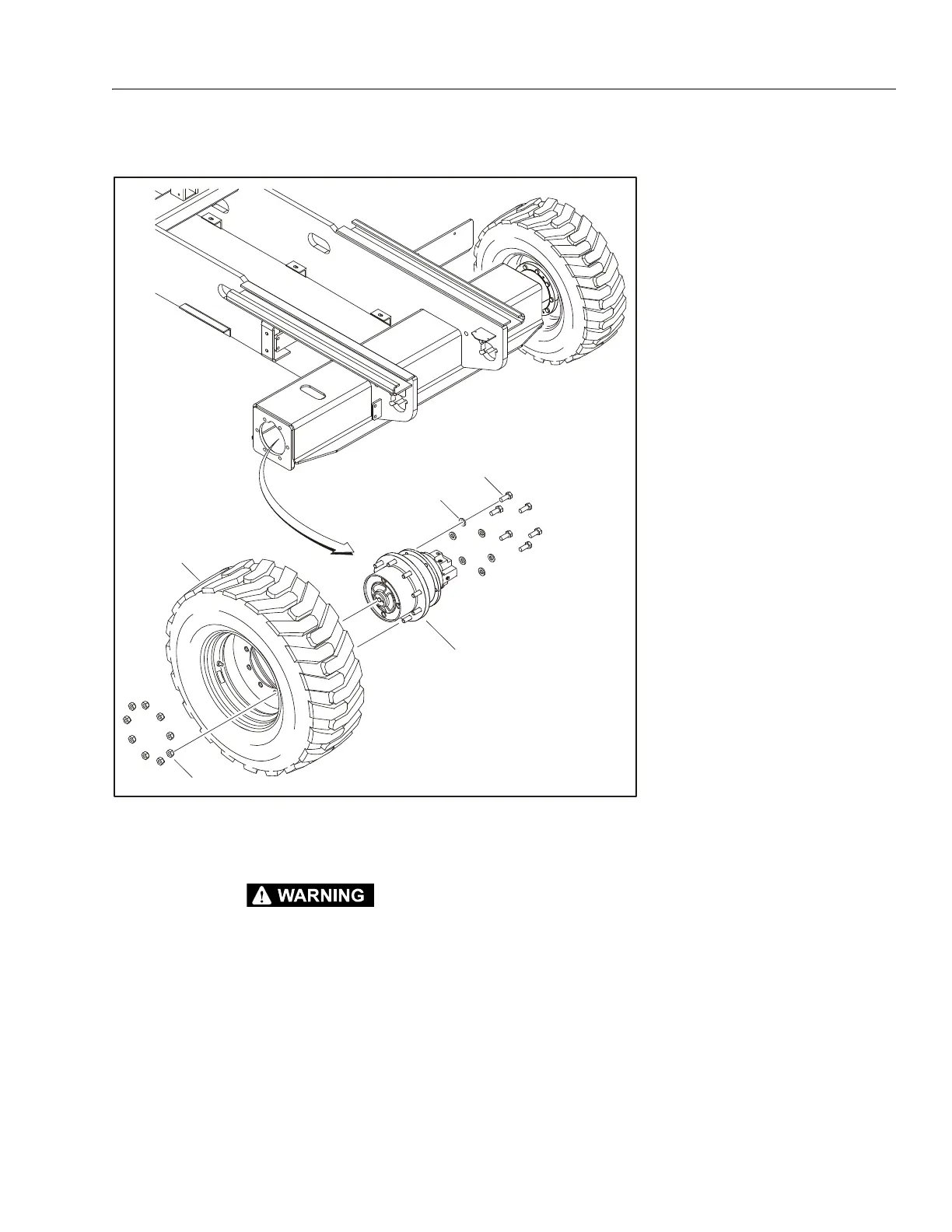
Figure 3-1. Drive Assembly (Bosch Rexroth )
1. Tire & Rim
2. Lugnuts
3. Drive Motor/Hub Assembly
(Bosch Rexroth)
4. Bolt, 5/8"-11NC x 1 1/2"
5. Hardened Washer
NOTE: Rear Axle Shown