SECTION 4 - HYDRAULICS
3121642 – JLG Lift – 4-29
charge pressure. If any component shows signs of wear,
scratching or pitting, replace it.
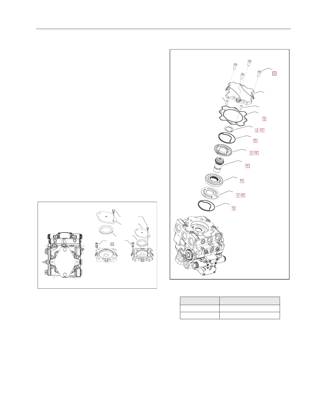
REASSEMBY:
11. Install new seals (S300) in the valve (S250) and pressure-
balance (S200) plates.
12. Install valve plate (S250) in the same orientation as
removed.
13. Lubricate and install charge pump (S100) and outer ring
(S150).
14. Install charge pump coupling (K200).
15. Install pressure balance plate (S200) in the same orienta-
tion as removed.
16. Install the thrust washer (K500). Coated side goes
toward charge pump coupling (K200).
17. Install a new cover gasket. (K150). If removed, install
guide pins (K450).
18. Install the auxiliary pad or charge pump cover and cap
screws. Using a 10mm internal hex wrench, torque the
cap screws (K400) to 68 lb-ft (92 Nm). Torque in
sequence below.
19. Reinstall auxiliary pump or pad seal (K250) and shipping
cover (K300).
.
SAE B
SAE A
K400
8 mm
K300
K350
(see table)
K250
Auxilliary pads
1
2
3
4
Torque sequence
Cover Screw K350
Cover Pad Wrench Size; Torque
A 17 mm; 35 lb-ft (48 Nm)
B, C 19 mm; 58 lb-ft (77 Nm)
G450
Charge pump removal/installation