Table 68 on page 556 describes the different scenarios in which the Martini circuit
configuration is supported, when Ethernet raw mode encapsulation is configured on
the S-VLAN interfaces.
Table 68: Martini Circuit Scenarios with Ethernet Raw Mode
Whether scenario is
supported, when raw
mode is not configured
on the S-VLAN
interface
Receiving CE Device
(CE2)
MPLS network
between local and
remote routers, PE1
and PE2Sending CE device (CE1)
Case
number
SupportedS-VLAN-AwareS-VLAN-AwareS-VLAN-Aware1
SupportedS-VLAN-AwareS-VLAN-UnawareS-VLAN-Aware2
UnsupportedS-VLAN-UnawareS-VLAN-AwareS-VLAN-Aware3
SupportedS-VLAN-UnawareS-VLAN-UnawareS-VLAN-Aware4
UnsupportedS-VLAN-UnawareS-VLAN-AwareS-VLAN-Unaware5
SupportedS-VLAN-UnawareS-VLAN-UnawareS-VLAN-Unaware6
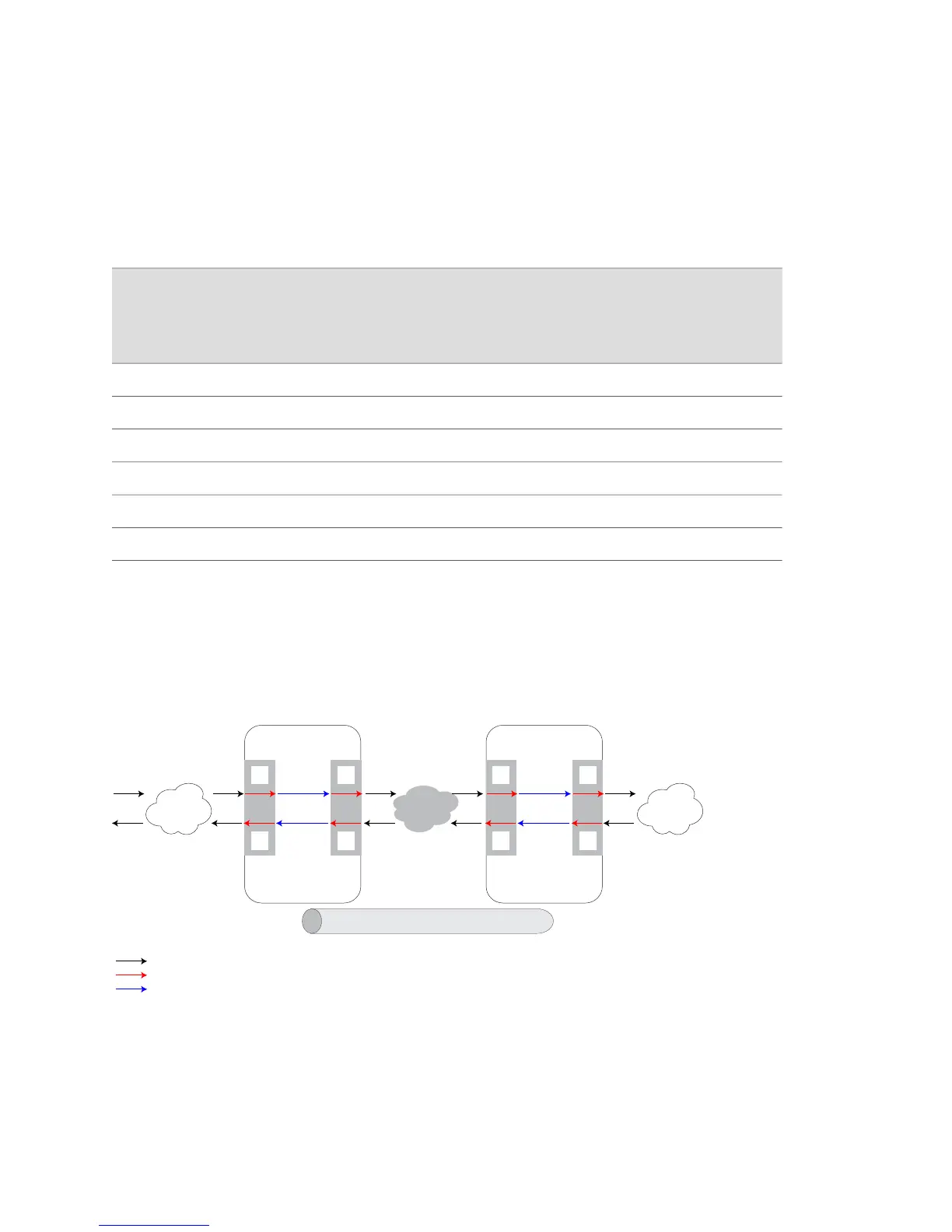
Figure 125 on page 556 shows the transmission of Ethernet packets over a Martini
circuit with ES2 4G, GE-2, GE/FE, ES2 10G, ES2 10G Uplink, and ES2 10G ADV LMs.
The different processing points inside the PE-facing routers are denoted as A, B, C,
and D.
Figure 125: Ethernet Packet Distribution over Martini Circuits
MPLS network
g016509
A
D
B
C
RT1
RT2
MPLS Edge Router 1
PE1
Line
module
Line
module
MPLS tunnel
Layer 2 services
C
B
D
A
RT2
RT1
MPLS Edge Router 2
PE2
Line
module
Line
module
Layer 2 services
External networ k connections
Internal forwarding paths
Router-fabric traversal
Consider a scenario in which Ethernet raw mode is not enabled on the S-VLAN
subinterface of the PE-facing devices. When a packet reaches the S-VLAN subinterface
on an ingress line module, point A, inside PE1, all packets, regardless of whether
they are tagged or not, are forwarded to the subinterface on the egress line module,
B, inside PE1 without any change. This behavior applies to both ES2 4G LMs, ES2
556 ■ Ethernet Raw Mode Encapsulation for Martini Layer 2 Transport Examples
JUNOSe 11.1.x BGP and MPLS Configuration Guide
 Loading...