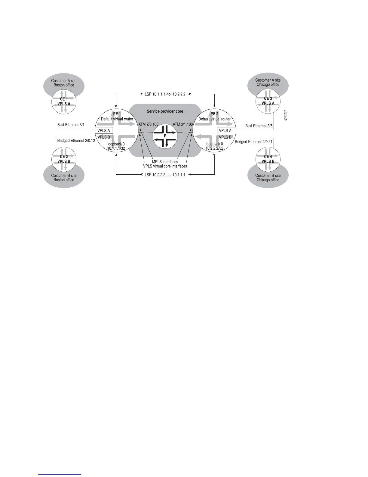
Figure 129: Topology for VPLS Configuration Example with BGP Signaling
Topology Overview of VPLS with BGP Signaling
The sample topology in Figure 129 on page 602 includes two VPLS domains, VPLS A
and VPLS B. VPLS A connects CE 1, at the edge of Customer A’s Boston site, with
CE 3, at the edge of Customer A’s Chicago site. Similarly, VPLS B connects CE 2, at
the edge Customer B’s Boston site, with CE 4, at the edge of Customer B’s Chicago
site.
The E Series routers in the topology, PE 1 and PE 2, each participate in both the
VPLS A domain and the VPLS B domain. The example configures a total of four
separate VPLS instances, one for each VPLS domain in which the PE router
participates. The instances for the VPLS A domain are named vplsA, and the instances
for the VPLS B domain are named vplsB.
For each VPLS instance, an Ethernet or bridged Ethernet network interface provides
a connection to the associated CE device. Each VPLS instance maintains its own set
of forwarding tables and filters to learn the network topology, in a manner that is
similar to a bridge group used for transparent bridging.
Each PE router in the sample topology also has an ATM core-facing interface that
connects it to the provider (P) router in the service provider core. You must configure
MPLS LSPs on the core-facing interfaces to connect PE 1 and PE 2 through the P
router across the service provider core. Finally, you must configure BGP on both PE 1
and PE 2 to provide signaling for both VPLS domains.
After you configure the bridging, MPLS, and BGP components of VPLS, the router
automatically generates a VPLS virtual core interface for each VPLS instance. The
VPLS virtual core interface represents all of the MPLS tunnels from the router to the
remote VE device.
602 ■ VPLS Configuration Example with BGP Signaling
JUNOSe 11.1.x BGP and MPLS Configuration Guide
 Loading...