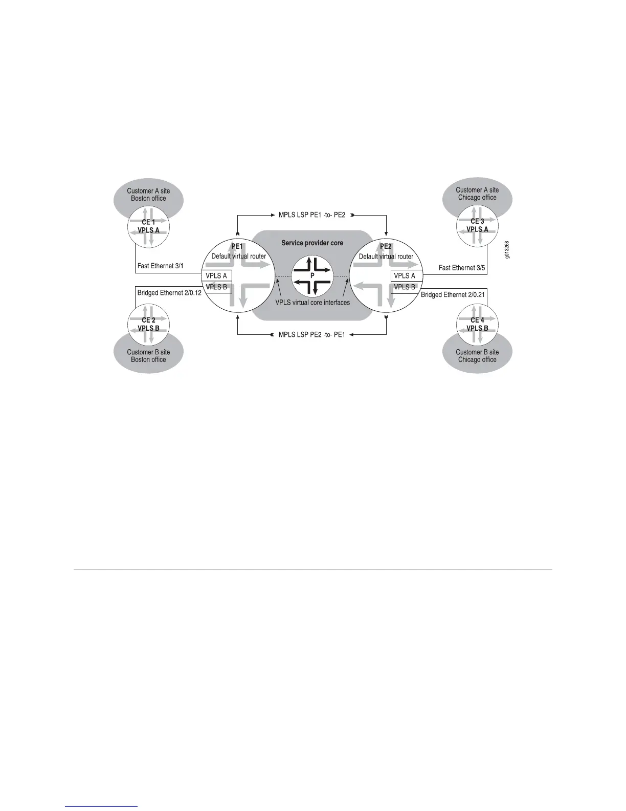
Figure 128 on page 576 illustrates an example of a simple VPLS topology. The basic
topology of a VPLS network is the same regardless of whether BGP signaling or LDP
signaling is used.
Figure 128: VPLS Sample Topology
Related Topics ■ BGP Signaling for VPLS on page 579
■ Configuration Tasks for VPLS with BGP Signaling on page 590 in Configuring VPLS
on page 589
■ LDP Signaling for VPLS on page 579
■ Configuration Tasks for VPLS with LDP Signaling on page 605 in Configuring VPLS
on page 589
■ Configuring BGP-MPLS Applications on page 379
■ Configuring VPWS on page 657
VPLS Components
As illustrated in Figure 128 on page 576, a typical VPLS topology consists of the
following components.
VPLS Domains
Typically, a VPLS domain is associated with customers who want to use Ethernet-based
layer 2 VPNs to connect geographically dispersed sites in their organization across
an MPLS-based service provider core, also known as an MPLS backbone. Each VPLS
domain consists of the set of PE routers running the corresponding VPLS instance
that participates in that domain. In BGP-signaled VPLS, a VPLS domain is identified
by the route target extended community, similarly to how a layer3 VPN domain is
identified in layer 3VPNs.
576 ■ VPLS Components
JUNOSe 11.1.x BGP and MPLS Configuration Guide
 Loading...