VPWS provides the same services as layer 2 over MPLS except for CE-side
load-balancing. The main differences between the VPWS and L2 over MPLS services
are signaling, autodiscovery, and configuration.
A VPWS L2VPN can have either a full-mesh or a hub-and-spoke topology. The
tunneling mechanism in the core network typically is MPLS. However, VPWS can
also use other tunneling protocols, such as GRE. VPWS is similar to Martini layer 2
services over MPLS, and employs a similar encapsulation scheme for forwarding
traffic.
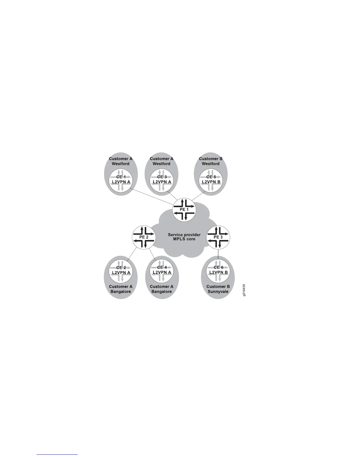
Figure 131 on page 646 illustrates an example of a simple VPWS L2VPN topology.
Figure 131: VPWS Sample Topology
In this example, the service provider offers VPWS services to Customer A and
Customer B. Customer A wants to create a full mesh of point-to-point links between
Westford and Bangalore. Customer B needs only a single point-to-point link between
Westford and Sunnyvale. The service provider uses BGP and MPLS signaling in the
core, and creates a set of unidirectional pseudowires at each provider edge (PE)
router to separately cross-connect each customer’s layer 2 circuits.
In order to provision this service, the provider configures two VPWS L2VPNs, L2VPN
A and L2VPN B. An encapsulation type is configured for each VPWS L2VPN. All
interfaces in a given VPWS L2VPN must be configured with the VPWS L2VPN’s
encapsulation type. The layer 2 interfaces that connect the PE router and CE device
pairs are configured to be members of the corresponding VPWS L2VPN, L2VPN A
or L2VPN B.
Local and remote site information for the interfaces identifies the cross-connect.
Local cross-connects are supported when the interfaces that are connected belong
646 ■ VPWS Overview
JUNOSe 11.1.x BGP and MPLS Configuration Guide