EasyManuals Logo

Keithley 2700 User Manual

Keithley 2700
500 pages
To Next Page IconTo Next Page
To Previous Page IconTo Previous Page
Page #218 background imageLoading...
Page #218 background image
Model 2700 Multimeter/Switch System User’s Manual Scanning 7-5
NOTE The trigger model in Figure 7-2 also applies for bus operation. See “Remote
programming — scanning,” page 7-26, for differences between front panel and
remote scanning.
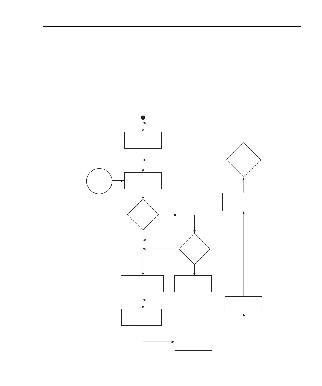
For the following discussion, refer to Figure 7-1 for STEP operation, and
Figure 7-2 for SCAN operation.
Figure 7-1
Trigger model with STEP function
Enable Scan
Control
Source
Immediate
External
Timer
Event
Detection
Output
Trigger
Another
Reading
?
Trigger
Counter
(Reading Count)
Yes
No
Close First
Chan in List
Open Last Chan
Close Next Chan
in List
Ratio/Chan
Average Delay
Measurement
Process
Device Action
Yes
Timer >
Delay
?
Timer
Enabled
?
Yes
No
Timer
Bypass
No
Delay
(Auto or Manual)
Timer

Table of Contents

Other manuals for Keithley 2700

Questions and Answers:

Question and Answer IconNeed help?

Do you have a question about the Keithley 2700 and is the answer not in the manual?

Keithley 2700 Specifications

General IconGeneral
TypeDigital Multimeter
Measurement FunctionsDC Voltage, AC Voltage, DC Current, AC Current, Resistance, Frequency, Temperature
DC Voltage Range100 mV to 1000 V
AC Voltage Range100 mV to 750 V
Frequency Range3 Hz to 500 kHz
Temperature Range-200°C to +1372°C
DisplayVacuum Fluorescent Display
ConnectivityIEEE-488, RS-232
Channels10
Power Supply100V to 240V AC, 45Hz to 66Hz
DC Current Range10 µA to 3 A
AC Current Range10 µA to 3 A
Temperature MeasurementThermocouple, RTD

Related product manuals