9-16 Limits and Digital I/O Model 2700 Multimeter/Switch System User’s Manual
Limit 1 will be used to test for the 1% tolerance and Limit 2 will be used to test for the 5%
tolerance.
The resistance values for the 1% and 5% tolerances are calculated as follows:
R
1%
= 100Ω × 1% R
5%
= 100Ω × 5%
= 100Ω × 0.01 = 100Ω × 0.05
= 1Ω = 5Ω
The high and low limits are then calculated as follows:
HI Limit 1 = 100Ω + R
1%
HI Limit 2 = 100Ω + R
5%
= 100Ω + 1Ω = 100Ω + 5Ω
= 101Ω = 105Ω
LO Limit 1 = 100Ω – R
1%
LO Limit 2 = 100Ω – R
5%
= 100Ω – 1Ω = 100Ω – 5Ω
= 99Ω = 95Ω
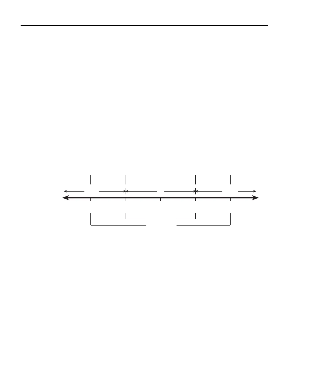
The limits are illustrated in Figure 9-7.
Figure 9-7
Limits to sort 100Ω resistors (1%, 5%, and >5%)
Front Panel Operation — For front panel operation, the INSIDE beeper mode must be
used. A normal pitch beep and the message IN indicates that the resistor is within the 1%
tolerance limit (
Figure 9-7). This 1% resistor belongs in Bin 1. A raspy beep and the “1”
message indicates that the resistor is >1% tolerance but <5% tolerance. This 5% resistor
belongs in Bin 2. For resistors >5%, no beep will sound. Place these resistors in Bin 3.
100Ω 101Ω
HI1
105Ω
HI2
95Ω
LO2
99Ω
LO1
Limit 1 (1%)
Limit 2 (5%)
LOW IN
HIGH
Beep
(Normal Pitch)
Beep
(Low Pitch)
Beep
(Low Pitch)
No Beep
No Beep

 Loading...


