11-14 Status Structure Model 2700 Multimeter/Switch System User’s Manual
Operation event register
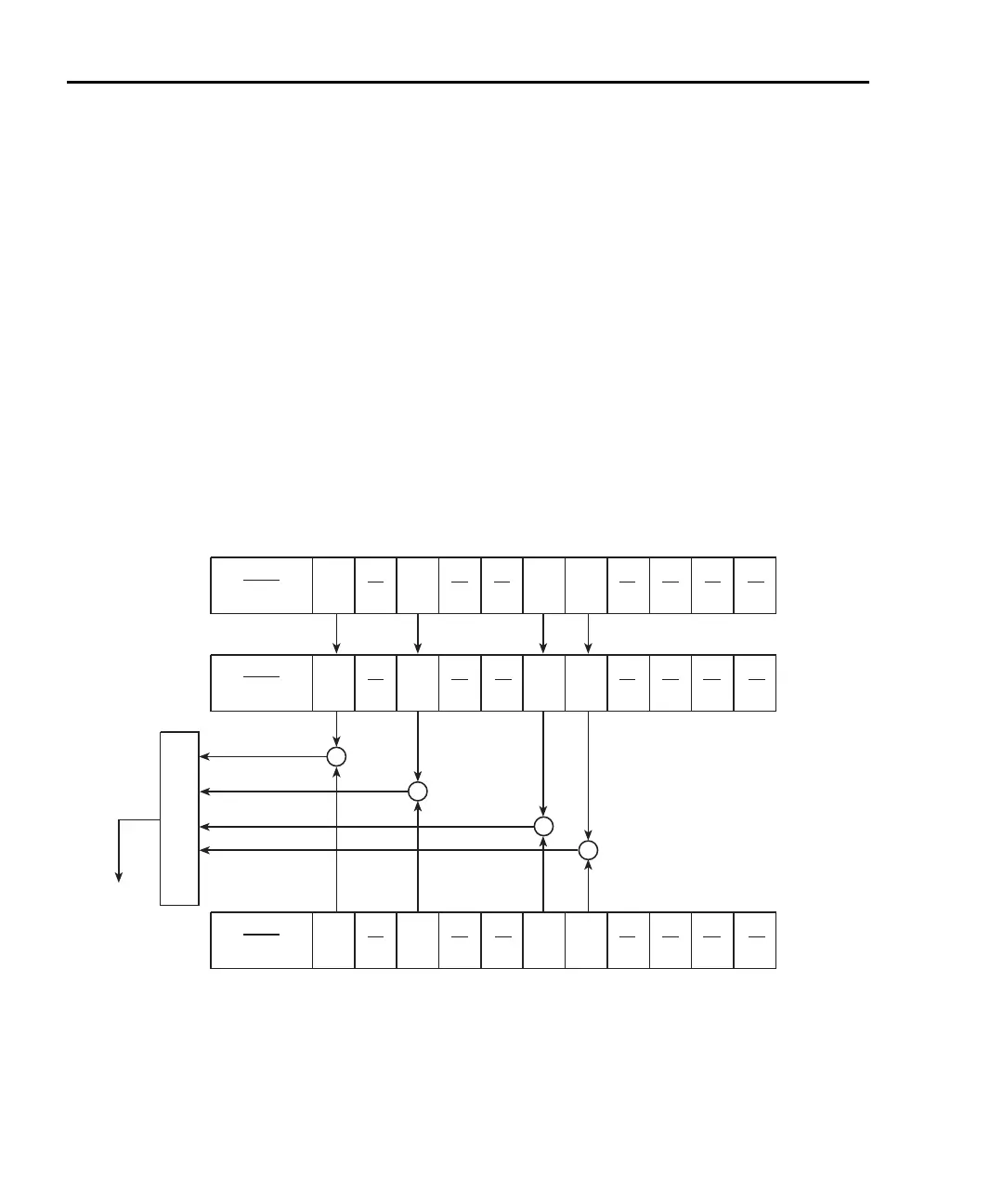
The bits of the Operation Event Register (Figure 11-5) are described as follows:
• Bits B0 through B3 — Not used.
• Bit B4, Measuring (Meas) — Set bit indicates that the instrument is performing a
measurement.
• Bit B5, Waiting for Trigger (Trig) — Set bit indicates that the Model 2700 is in
the trigger layer waiting for a trigger event to occur.
• Bits B6 and B7 — Not used.
• Bits B8, Filter Settled (Filt) — Set bit indicates that the filter has settled or the
filter is disabled.
• Bit B9 — Not used.
• Bit B10, Idle State (Idle) — Set bit indicates the Model 2700 is in the idle state.
• Bits B11 through B15 — Not used.
Figure 11-5
Operation event status
OR
Idle = Idle state
Filt = Filter Settled or Disabled
Trig = Triggering
Meas = Measuring
& = Logical AND
OR = Logical OR
(B15 - B11)
Idle
(B10) (B9)
Filt
(B8) (B7) (B6)
Trig
(B5)
Meas
(B4) (B3) (B2) (B1) (B0)
(B15 - B11)
Idle
(B10) (B9) (B8) (B7) (B6)
Trig
(B5)
Meas
(B4) (B3) (B2) (B1) (B0)
Operation
Event
Enable
Register
To
Operation
Summary
Bit (OSB) of
Status Byte
Register.
(B15 - B11)
Idle
(B10) (B9)
Filt
(B8) (B7) (B6)
Trig
(B5)
Meas
(B4) (B3) (B2) (B1) (B0)
Operation
Condition
Register
Filt
&
&
&
&
Operation
Event
Register

 Loading...


