Model 2700 Multimeter/Switch System User’s Manual Model 7700 Connection Guide B-7
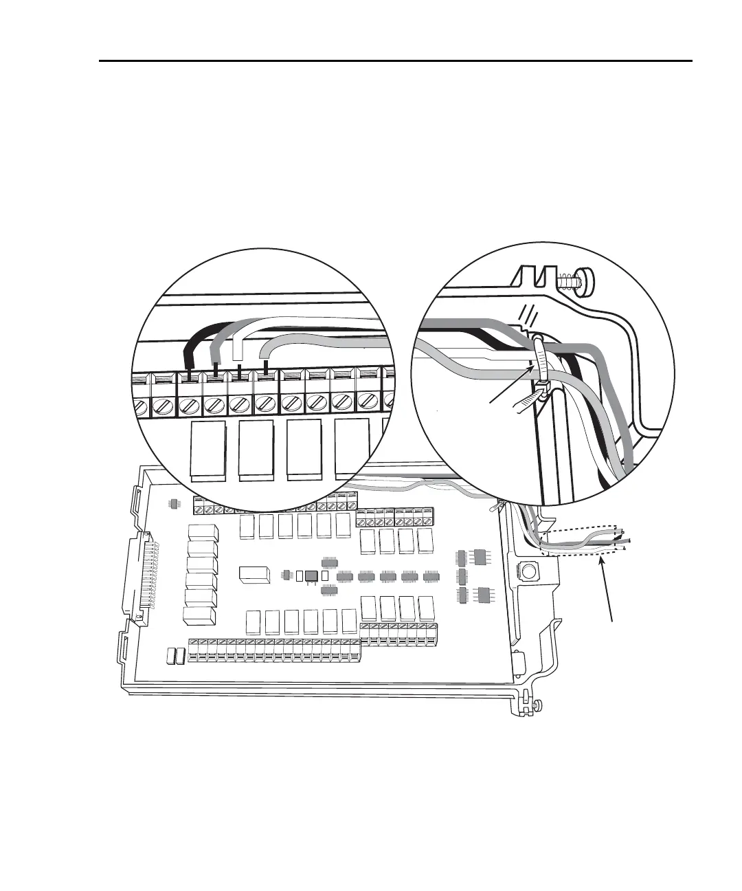
3. Using a small flat-blade screwdriver, loosen terminal screws and install wires as
desired. (
Figure B-4 shows connections to channels 1 and 2.)
4. Route wire along wire-path and secure with cable tie as shown.
5. Fill in a copy of the connection log (Table B-1) and affix it to the module cover.
6. Close and lock cover.
Figure B-4
Wire dressing
Supplementary
Insulation
CH7
H L
CH8
H L
CH9
H L
CH10
H L
H L
CH21
H L
CH22
AMPS
LO
H L
CH11
H L
CH12
H L
CH13
H L
CH14
H L
CH15
H L
CH16
H L
CH17
H L
CH18
H L
CH19
H L
CH20
INPUT SENSE
H L H L
CH1
H L
CH2
H L
CH3
H L
CH4
H L
CH5
H L
CH6
H L
SENSE
(OHMS, 4-WIRE)
INPUT
(V, 2-WIRE)
SENSE
H L
CH1
H L
CH2
H L
CH3
H L
CH4
H L
C
H

 Loading...


