Model 2700 Multimeter/Switch System User’s Manual Measurement Considerations E-7
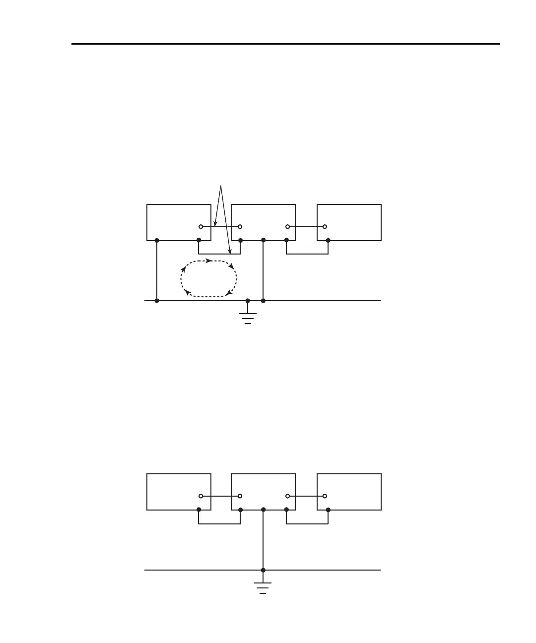
path such as power line ground. As shown in Figure E-2, the resulting ground loop causes
current to flow through the instrument LO signal leads and then back through power line
ground. This circulating current develops a small but undesirable voltage between the LO
terminals of the two instruments. This voltage will be added to the source voltage,
affecting the accuracy of the measurement.
Figure E-2
Power line ground loops
Figure E-3 shows how to connect several instruments together to eliminate this type of
ground loop problem. Here, only one instrument is connected to power line ground.
Ground loops are not normally a problem with instruments like the Model 2700 that have
isolated LO terminals. However, all instruments in the test setup may not be designed in
this manner. When in doubt, consult the manual for all instrumentation in the test setup.
Figure E-3)
Eliminating ground loops
Signal Leads
Instrument 1
Power Line Ground
Ground
Loop
Current
Instrument 2 Instrument 3
Instrument 1
Power Line Ground
Instrument 2 Instrument 3

 Loading...


