146 Keysight N9010A EXA Service Guide
RF Section Troubleshooting (RF/Microwave Analyzers)
RF Section Description
A13 RF Front End Assembly
This assembly is a self-contained microcircuit that is repaired at the assembly
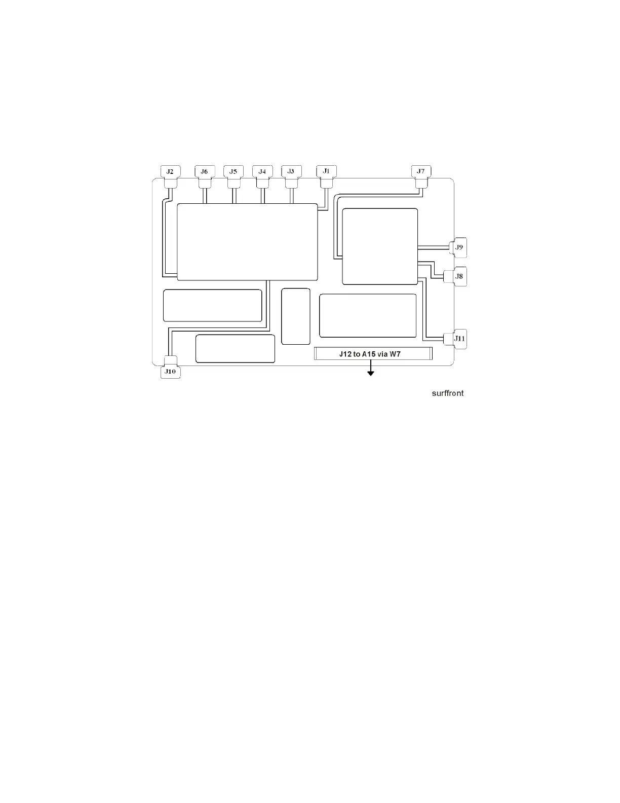
level. See Figure 4-1.
Figure 4-1 A13 RF Front End Assembly View from Front Panel
This assembly contains the following circuits:
— Input Low-pass filter (RF input signals < 3.6 GHz)
—Low Band Limiter
— Optional Electronic Attenuator (0-24 dB attenuation control)
— Optional Low Band Preamplifier
— RF Mixer #1 (RF input signals < 3.6 GHz)
— 1st L.O. Sub-system (3.8 GHz to 8.7 GHz)
— 1st I.F. Amplifier (5122.5 MHz)
— I.F. Band pass filter (5122.5 MHz)
— I.F. Low-pass filter (5122.5 MHz)
— Mixer #2 (RF input signals 3.6 GHz to 13.599 GHz)
— Microwave Input Amplifier
— Mixer #3 (RF input signals 13.6 GHz to 26.5 GHz)
— 2nd I.F. Amplifier (322.5 MHz)
— Microwave L.O. Sub-system (3.8 GHz to 8.7 GHz)
— L.O. Doubler

 Loading...


