164 Keysight N9010A EXA Service Guide
RF Section Troubleshooting (RF/Microwave Analyzers)
Troubleshooting
To further test the YTF control current, select Amps on the DVM and place the
positive lead of the DVM on one of the YTF Coil Current P8 pins and the other
DVM lead to the other Coil Current pin.
If any of the preselector control currents do not match the levels shown in
Table 4-8, the most probable causes are a misaligned YTF or the A15 Front End
Control Assembly. Perform the YTF characterization (press System,
Alignments, More, Ad vanced, Characterize Preselector) and re-check the
control current at various center frequencies.
In order to measure the control current correctly, press Single on the analyzer in between each
measurement.
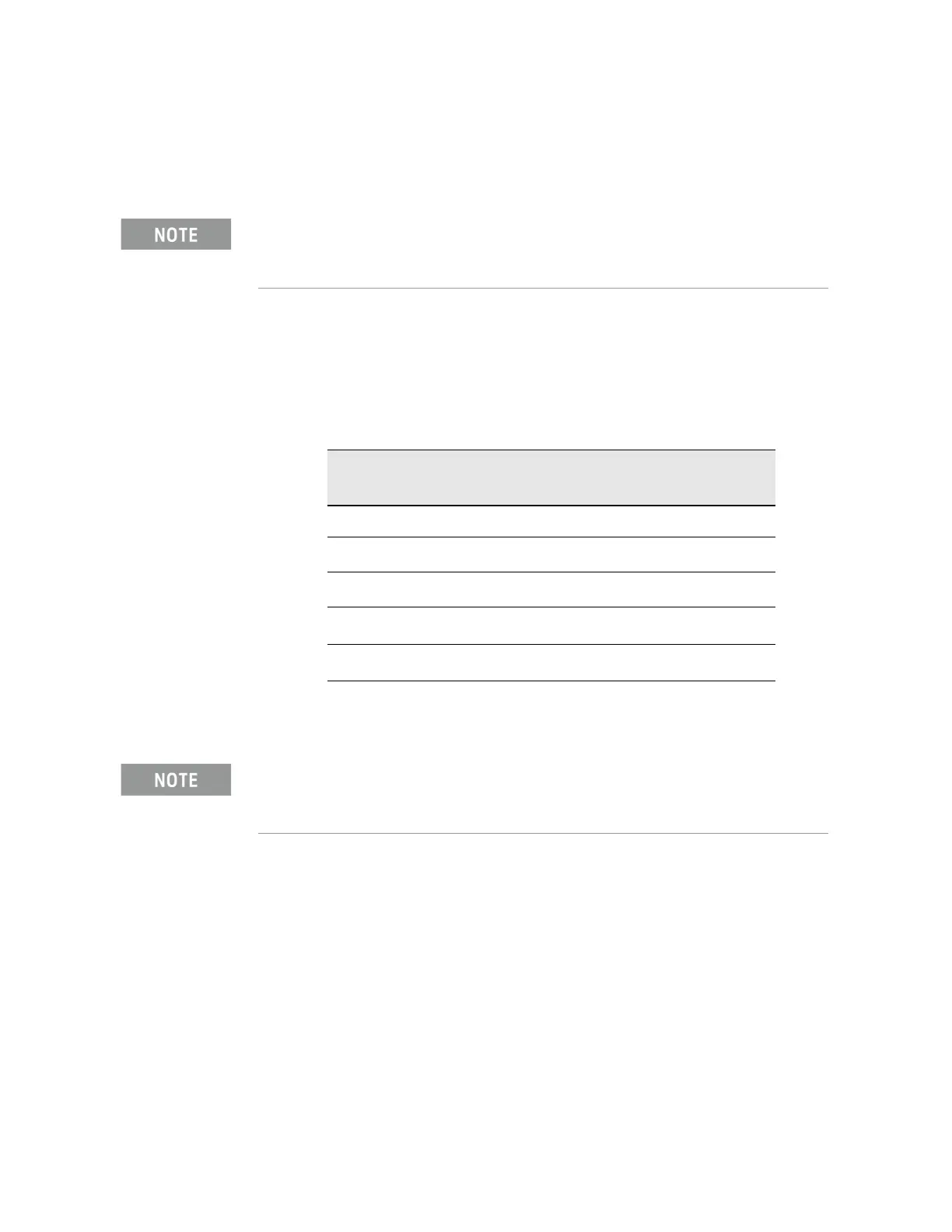
Table 4-8 YTF Tune Current
Center Frequency
(GHz)
Control Current
(mA)
Tolerance
(mA)
5.0 106 ±20
10
a
a. Options 513 and 526
215 ±25
15
b
b. Option 526
324 ±30
20
b
430 ±40
26
b
560 ±50
Tolerances should be used as a guideline. The true test is whether or not the analyzer will
function and meet published specification.

 Loading...


