168 Keysight N9010A EXA Service Guide
RF Section Troubleshooting (RF/Microwave Analyzers)
Troubleshooting
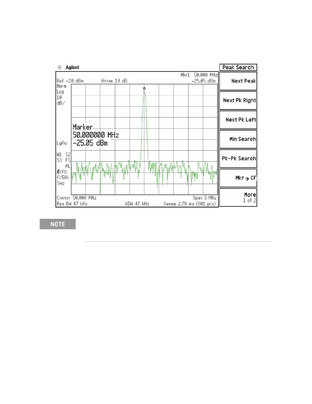
The level should be −25 dBm ± 2 dB as shown in Figure 4-14.
Figure 4-14 50 MHz Calibrator Signal on Output of Attenuator A
Press Mech Atten and enter 2 dB. The 50 MHz calibrator signal measured on
the functioning Spectrum Analyzer should measure 2 dB lower than the
previous step (~−27 dBm). Press Mech Atten and enter 4 dB. The 50 MHz
calibrator signal measured on the functioning Spectrum Analyzer should
measure an additional 2 dB lower than the previous step (~−29 dBm). If the
power levels measure correctly, reconnect W11 cable. If either of these levels is
incorrect, Input Attenuator A is the most probable cause, provided the control
logic from the A15 Front End Control Assembly was previously verified.
The paragraph which follows applies only to analyzers equipped with Option FSA, Fine Step
Attenuator.

 Loading...


